GE MEDICAL SYSTEMS
D
IRECTION 2380207, REVISION 7 LOGIQ™5 PRO SERVICE MANUAL
Chapter 5 Components and Functions (Theory) 5-19
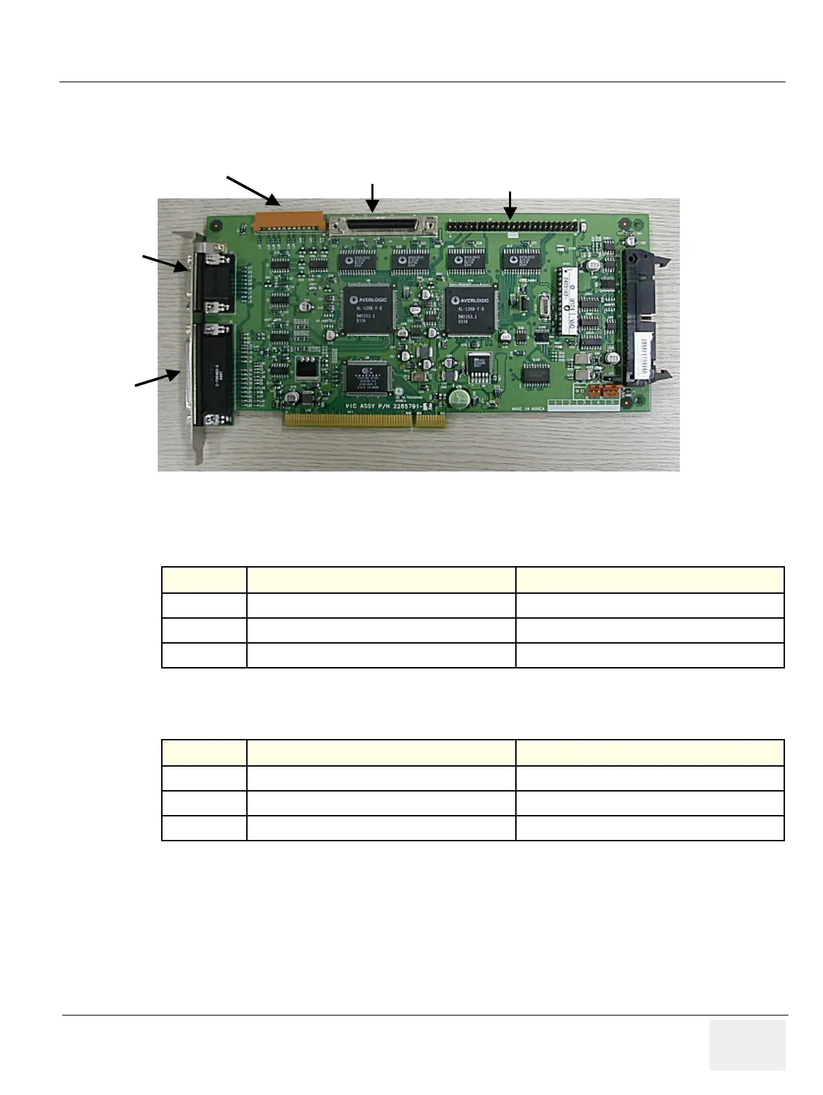
5-5-5-1 VIC Card I/O Signal
VIC card has many of I/O signal in connectors for system on/off function and peripheral interface
Figure 5-17 VIC Card
Table 5-2 Connector J1 (VGA input)
Signal Name Description Signal Path
R,G,B
Analog VGA signal
BEP Motherboard -> VGAtoVIC cable -> VIC
HS
VGA Horizontal Sync signal
BEP Motherboard -> VGAtoVIC cable -> VIC
VS
VGA Vertical Sync signal
BEP Motherboard -> VGAtoVIC cable -> VIC
Table 5-3 Connector J3 (VGA Output)
Signal Name Description Signal Path
R,G,B
Analog VGA signal
VIC -> Display CRT Monitor
HS
VGA Horizontal Sync signal
VIC -> Display CRT Monitor
VS
VGA Vertical Sync signal
VIC -> Display CRT Monitor
VGA
Input
J1
Signal I/O
For
Peripheral
J2
VGA
Output
J3
Signal I/O
J4
Signal I/O
to PC2IP
J5
Signal I/O to
Patient IO
J13
VGA
Input
J1
Signal I/O
For
Peripheral
J2
VGA
Output
J3
Signal I/O
J4
Signal I/O
to PC2IP
J5
Signal I/O to
Patient IO
J13


 To Next Page