GE MEDICAL SYSTEMS
DIRECTION 2380207, REVISION 7 LOGIQ™ 5 PRO SERVICE MANUAL
3 - 20 Section 3-6 - System Configuration
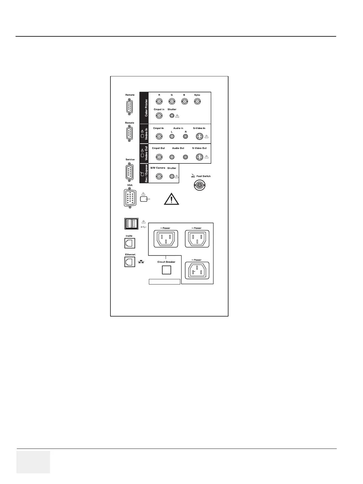
3-6-4 External I/O Connector Panel (cont’d)
This section indicates the pin assignment for each connector.
NOTE: Each outer (case) ground line of peripheral/accessory connectors are protectively grounded.
Signal ground lines are not isolated, except the Service port (3). All of signal lines (include signal
GND) of the Service port are isolated.
Figure 3-22 Rear Connector Panel
220-240V 500VA Max
Including front printer panel
1
2
Serial
1 2
 Loading...