CHAPTER 1: BEFORE YOU START
D20E ETHERNET I/O MODULE INSTRUCTION MANUAL GE INFORMATION 29
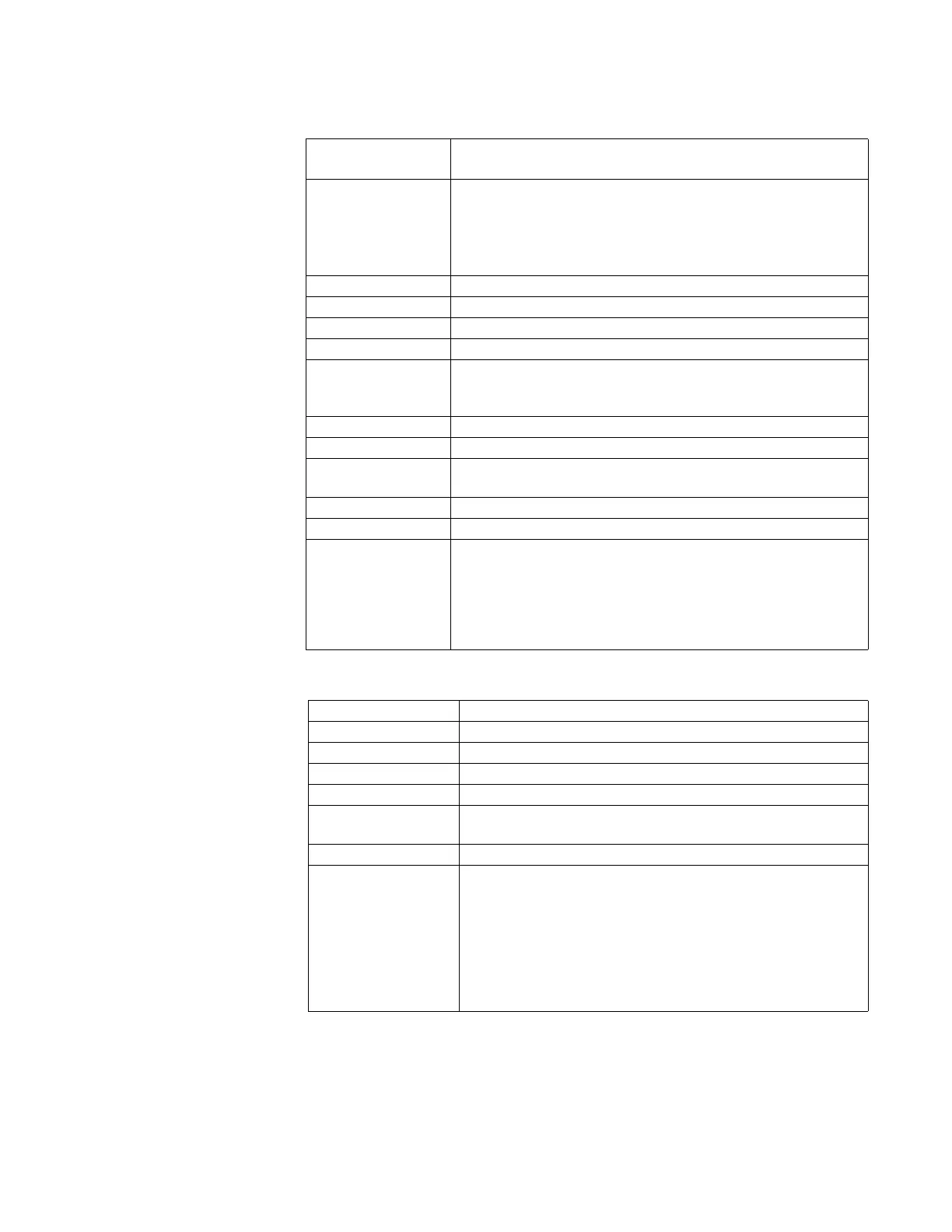
Analog inputs
Power supply
Number of Analog
Inputs
D20E-C: 16 differential inputs
D20E-A: 32 differential inputs
Input Options ±5.0 VDC, ±1.0 mA, ±5.0 mA, ±10.0 mA, ±20.0 mA
D20E Analog Input types are defined exclusively by the hard-wired scaling
resistor installed at the factory. The A/D is fixed at ± 5V. Normal scaling
parameters can be applied in the Publisher configuration.
Note: Refer to Chapter 1, Ordering guides section for complete set of
options currently available.
Accuracy ±0.1% FS (current), ±0.05% FS (voltage)
Input Impedance ≥1.0 M
Ω
(Voltage input)
Resolution 15-bit plus sign
Input Conversion Time 22 ms (per input)
Local Indications Blue LED ADC conversion:
• D20E-A
: 2 LEDs
• D20E-C: 1 LED
CMRR 90dB (at 50/60 Hz)
NMRR 60dB (at 50/60 Hz)
Insulation/Isolation 700 VDC
>100 M
Ω
Alarm High/Low alarm with pseudo digital input indication
Auto-Calibration 3-point reference
Conducted Immunity As per:
• IEEE C37.90.1
• IEC 61000-4-4
• IEC 61000-4-5
• IEC 61000-4-6
• IEC 61000-4-16
DC Input 20 to 60 VDC range, nominal 24/48 VDC
DC Input Mode Dual mirror inputs DC1 and DC2; single power supply
Polarity Protection Reverse input
Power 5 W typical
Current 0.25 A maximum
Insulation/Isolation 2250 VDC
>100 M
Ω
Local Indications DC1 and DC2 Blue LEDs; Power Supply output ON Red LED
Conducted Immunity As per:
• IEEE C37.90.1
• IEC 61000-4-4
• IEC 61000-4-5
• IEC 61000-4-6
• IEC 61000-4-16
• IEC 61000-4-17
• IEC 61000-4-29