D20E ETHERNET I/O MODULE INSTRUCTION MANUAL GE INFORMATION 77
D20E Ethernet I/O Module
Chapter 5: Connecting to Devices
and Networks
Connecting to Devices and Networks
This chapter provides guidelines for making physical connections between the D20E and
substation and network devices:
• D20E connectors on page 77
• Console port on page 78
• Network data communication on page 79
• Daisy-chaining D20E modules on page 82
D20E connectors
The side panel of the D20E model provides the following connectors (see Figure 12):
• Four RJ45 connectors
The two RJ45 connectors shown on the left side are for the LAN 2 or Ethernet™ 2
switch.
The two RJ45 connectors shown on the right side are for the LAN 1 or Ethernet™ 1
switch.
• One USB connector
The USB connector shown on the far-right allows you to connect a computer to a
D20E for device setup and servicing.
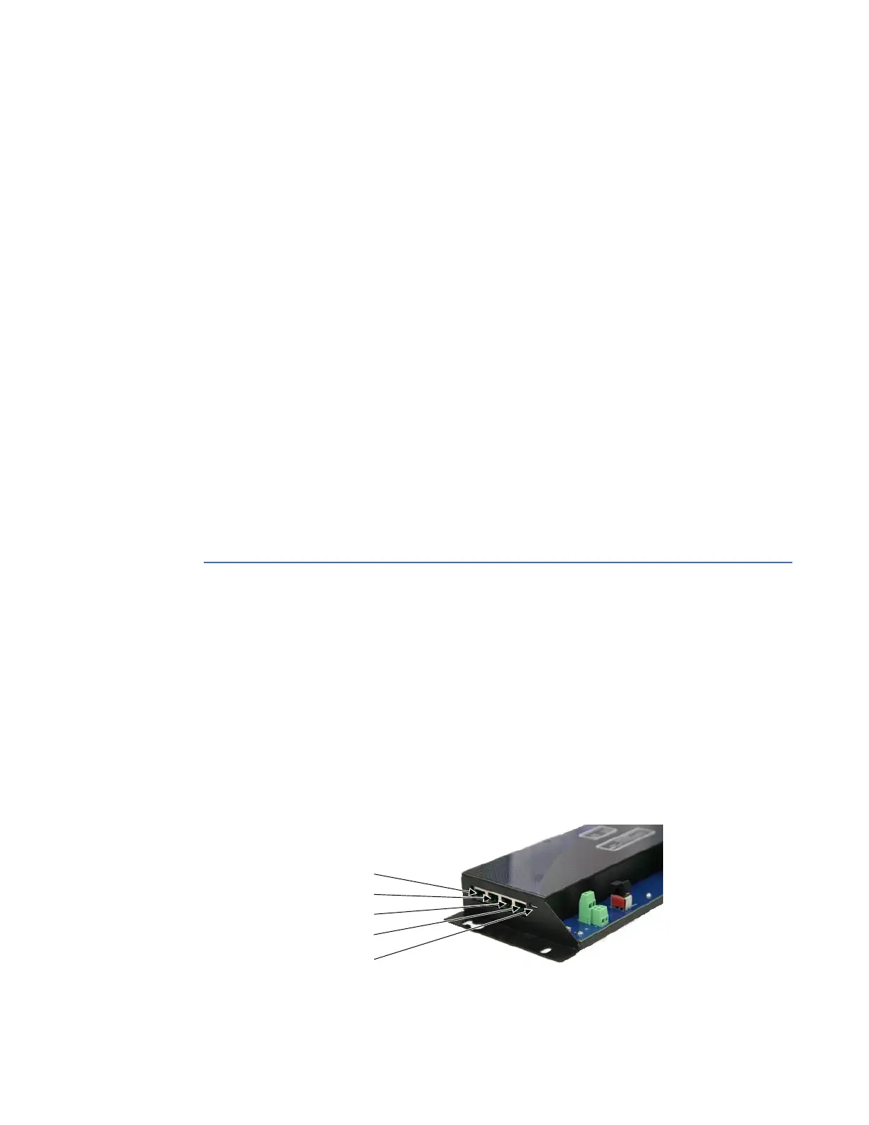
Figure 12: D20E side panel Ethernet and USB connectors
10/100 Mbps LAN#2
LAN #2 switched port
10/100 Mbps LAN#1
LAN #1 switched port
USB 2.0 port