GE COMPANY
DIRECTION 5472001-1EN, REVISION 6OPTIMA CT680 SERIES AND OPTIMA CT670 INSTALLATION MANUAL
Page 166 Section 6.0 - Electrical Power On & Ground Checks
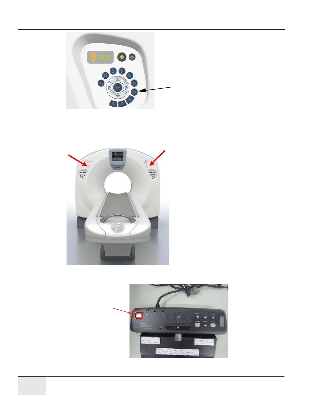
Figure 4-25 Reset buttons on Gantry Switch
Note: Emergency Stop buttons are located on the front of the gantry (2 in all), as noted in Figure 4-26.
Additionally, emergency stop buttons are provided on the Operator Console GSCB and PDU (see
Figure 4-27).
Figure 4-26 Gantry Emergency Stop Button Positions
Figure 4-27 GSCB Emergency Stop Button

 Loading...


