GE COMPANY
DIRECTION 5472001-1EN, REVISION 6OPTIMA CT680 SERIES AND OPTIMA CT670 INSTALLATION MANUAL
Page 174 Section 1.0 - Gantry Cover Removal
FAILURE TO DO SO WILL RESULT IN INSTABILITY DURING FRONT COVER
HANDLING.
5.) Insert top post into the base riser post. Align the key for complete engagement.
6.) Insert top post locking pin to secure both top and bottom sections.
7.) Reverse above steps to disassemble.
Note: For base storage only one (1) palm screw needs to be tightened. This will engage the bottom base
plate and the leg ends preventing the legs from unfolding during transport and storage.
Removal
1.) Position the table at its lowest position.
NOTICE Always turn OFF the HVDC before the 120 VAC. Turning OFF 120 VAC power before HVDC
power can result in equipment damage.
2.) Remove gantry side and top covers, if you have not already done so.
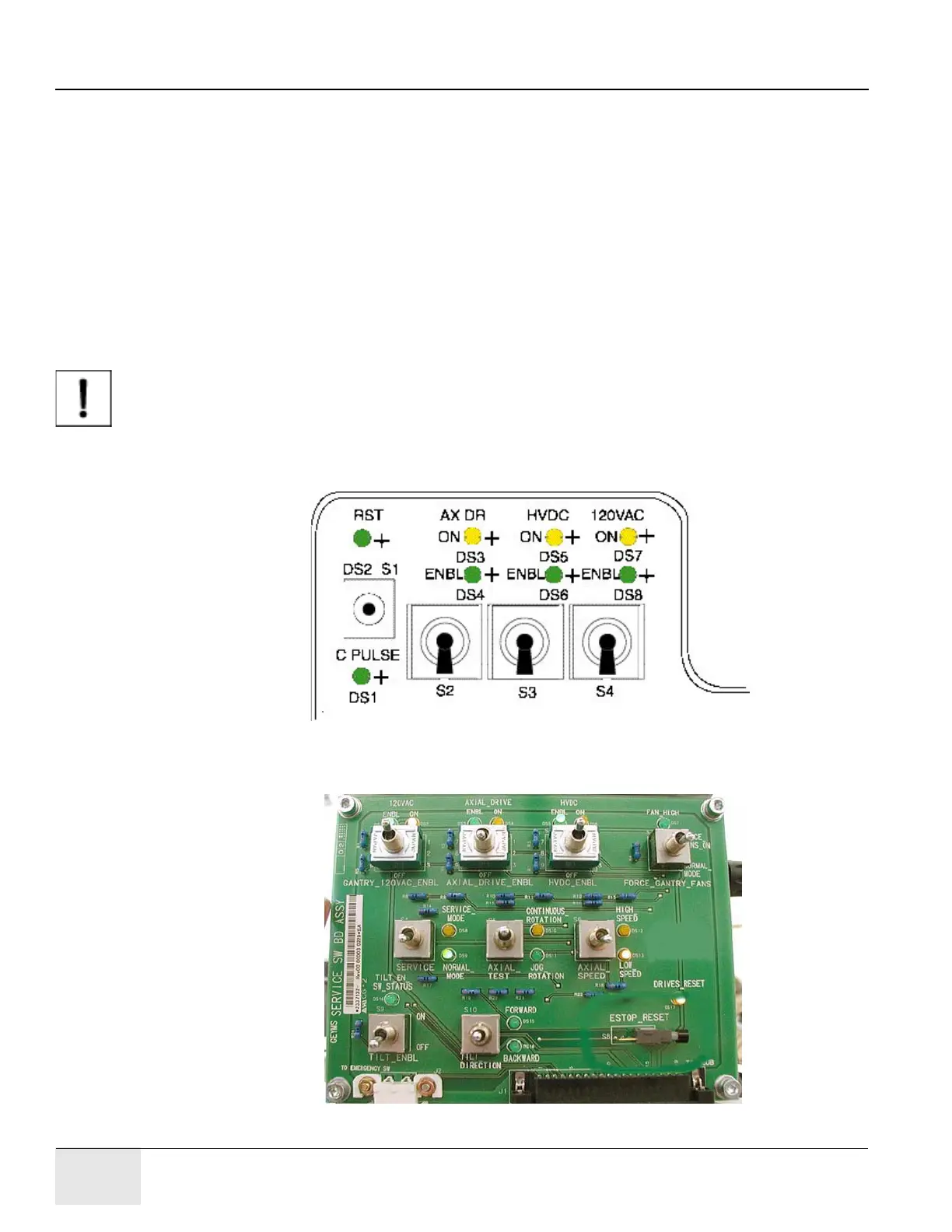
3.) Verify the three (3) power switches have been turned OFF (see Figure A-10).
Figure A-10 STC Power Switches
4.) Verify the three (3) power switches have been turned OFF (see Figure A-11).
Figure A-11 Service Switch Panel

 Loading...


