GE COMPANY
DIRECTION 5472001-1EN, REVISION 6OPTIMA CT680 SERIES AND OPTIMA CT670 INSTALLATION MANUAL
Chapter 1 - Position Subsystems Page 57
1 – Pos. Subsystems
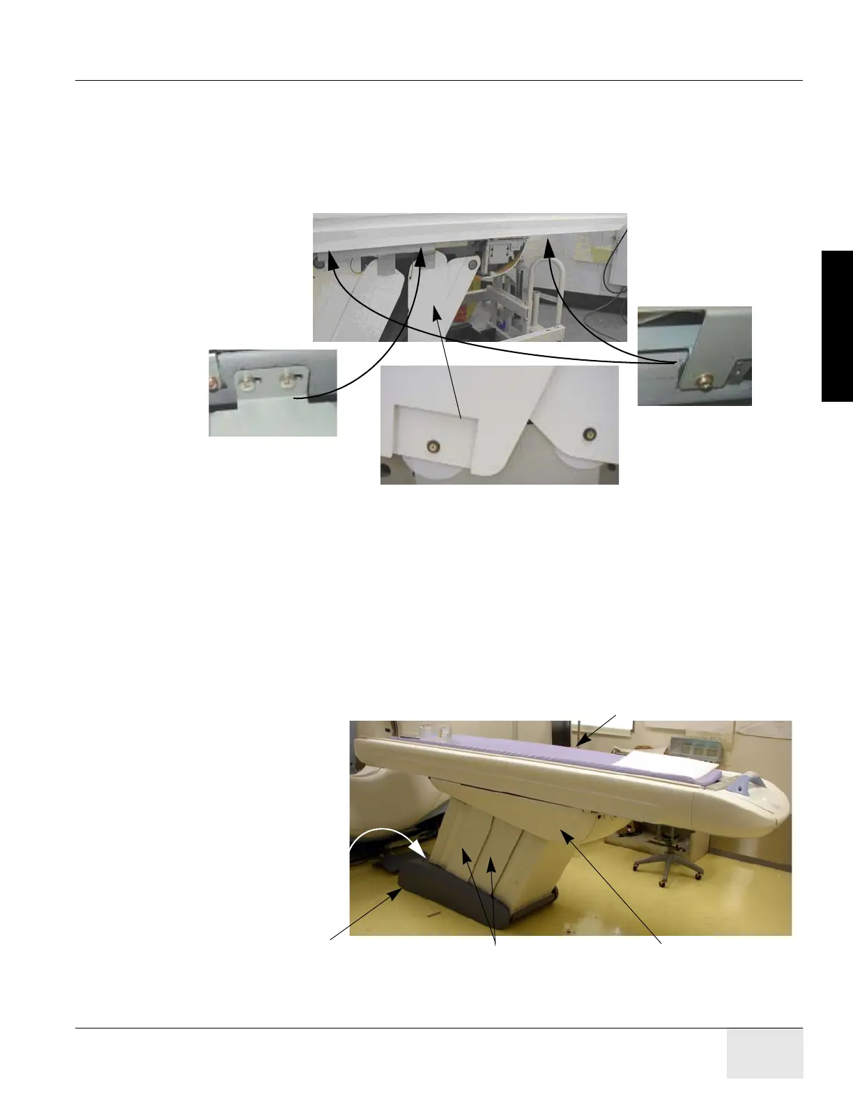
9.3.3 Table Cover Removal
1.) Remove the table right side cover, as shown in Figure 1-31.
a.) Removing the two screws on each end of the underside of the long side cover of the table.
b.) Slide each cover forward to unlatch, lift upward slightly to disengage the latches, and
remove the side cover. Doing this procedure will require patience and practice to remove
and replace this cover.
Figure 1-30 Table Covers
2.) The table is normally shipped with some of the side/vertical panels removed. If installed,
remove the four side panels, using a Pozi drive #1 screwdriver.
3.) Carefully lay the side panels on protective padding out of the way.
4.) Make sure that all four of the table levelers are on the floor. The table should set on the four
levelers with the dollies still installed.
5.) Carefully center the four levelers over the 4" (102mm) floor cutouts.
6.) Check that the front table base center line is on the chalk table center line.
7.) If still present, remove all packing materials and the table cradle pad from the table cradle.
Figure 1-31 Table Covers
Vertical Panel - Top
Vertical Panel - Bottom
Table Side Cover Screws
Front Base Cover
(in front of table base)
Left and Right
Base Covers
Left and Right
Vertical Side Covers
Left and Right
IMS Covers
Right Table Cradle Side Cover

 Loading...


