GE COMPANY
DIRECTION 5472001-1EN, REVISION 6OPTIMA CT680 SERIES AND OPTIMA CT670 INSTALLATION MANUAL
Page 56 Section 9.0 - Table Installation (GT1700V)
1.) Remove all the transportation packaging and boxes, except dollies, from the table. (See
Figure 1-27.) Leave a layer of packing material on the cradle to protect the cradle from
damage. (It can be removed during laser alignment of the table.)
Figure 1-27 Remove Table Packing
2.) Unpack the items and locate all of the items needed to install the table.
Note: The GT / VT table on dollies is approximately 118" long and may require additional room to
maneuver.
3.) Using the table centering and distance locator marks made earlier, wheel the table to its
approximate position relative to the gantry.
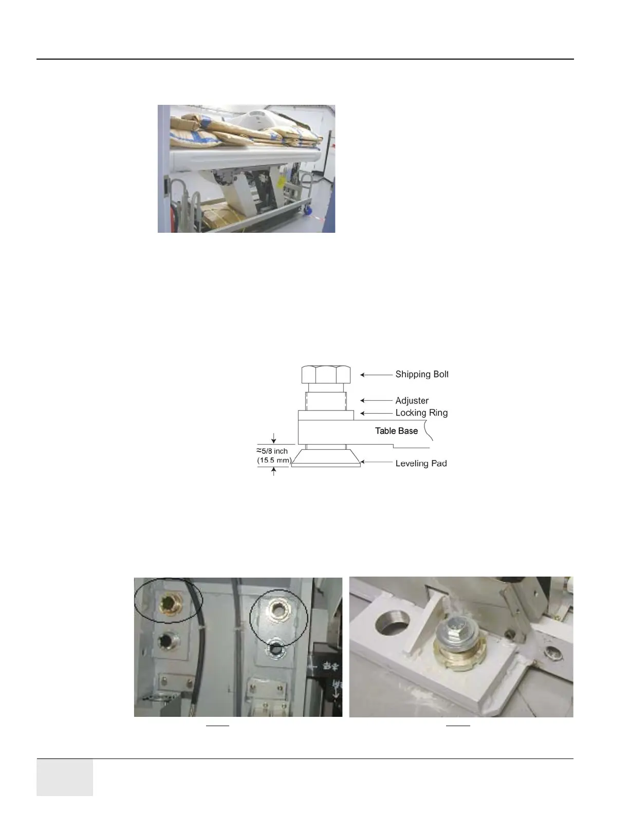
4.) Locate the table leveling pads inside the table in the back and on the side in the front. Preset
leveling pad heights to 5/8" (15.5mm). (See Figure 1-22.)
Figure 1-28 Table Base Leveling Pads (Starting Positions)
5.) Use a 1-5/8” socket and ½” ratchet to loosen the shipping bolt. Loosen the locking rings if
present.
6.) A 1-1/8" socket is used with the adjuster tool if needed to lower the adjuster.
7.) Use the dollies to evenly lower the table until it rests on the leveling pads using a ½”ratchet on
each end.
Figure 1-29 Adjusters and Lock Rings

 Loading...


