GE COMPANY
DIRECTION 5472001-1EN, REVISION 6OPTIMA CT680 SERIES AND OPTIMA CT670 INSTALLATION MANUAL
Chapter 1 - Position Subsystems Page 71
1 – Pos. Subsystems
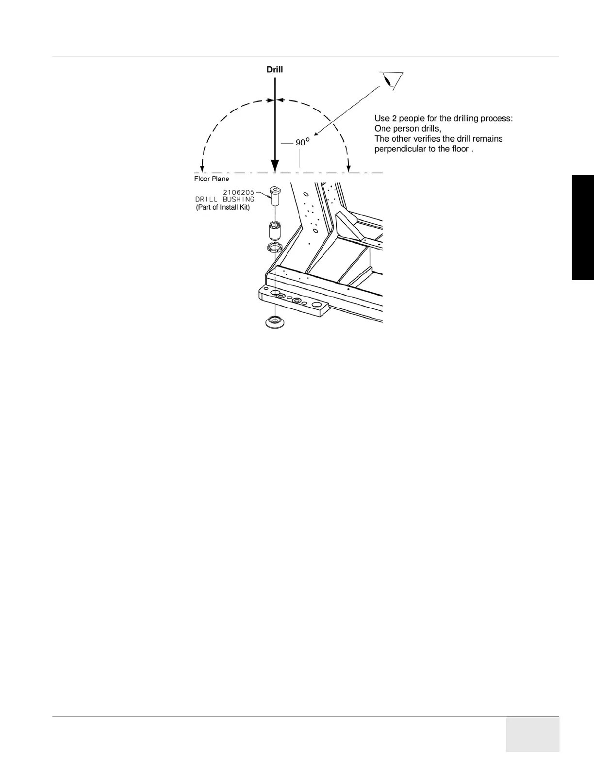
Figure 1-50 Drilling Position
5.) Place appropriate protection to prevent damage and dust contamination to electronic
assemblies.
6.) Place the drill bushing inside each adjuster, to keep the hole vertical and centered within the
adjuster.
- Use the drill bushing to center the anchor holes in all adjuster locations, to provide
maximum lateral alignment capacity when you center the cradle on isocenter during
subsequent system testing.
- Take care not to injure yourself on the gantry cover brackets.
7.) Drill the holes perpendicular to the floor.
Important - Follow these guidelines when drilling anchor holes:
- While one person drills the holes, position a second person to watch the relationship
between the drill bit and floor. Make sure the bit remains absolutely perpendicular to the
floor throughout the drilling operation.
- Always use the mechanical guide when drilling.
- Stop drilling every 15 or 20 seconds and clear the hole of debris. This lets the drill bit cool
and helps to prevent binding of the drill bit.
- Vacuum while drilling to keep gantry and table as free of dust contamination as possible.
Place the funnel tip or long extension tip inside the hole.
A drywall dust filter must be used on the vacuum.
- Drill each hole until the mark on the drill bit is even with the top of the drill bushing. All
holes must be have a depth specified in Table 1-3, as measured from the top of the
adjuster to the bottom of the hole. (See Figure 1-57, on page 78) Use an upside-down
anchor to check the hole depth.

 Loading...


