80209C_MHW_850-1650-1850_01-2020_ENG_pag. 222
OPEN
CLOSE
MAX
SIGNAL
MIN
+
VP
+
1V
-
Ph L+
Mp N-
OUT1
OUT2
OUT3
PWR
37
38
39
40
41
42
43
44
45
46
47
48
36
35
34
33
32
31
30
29
28
27
26
25
12
11
10
9
8
7
6
5
NO
C
NO
C
NO
C
M
Power neutral
Open command (phase)
Close command (phase)
Position reverse potentiometer
Auxiliary input
for models with Auxiliary Input option = 2
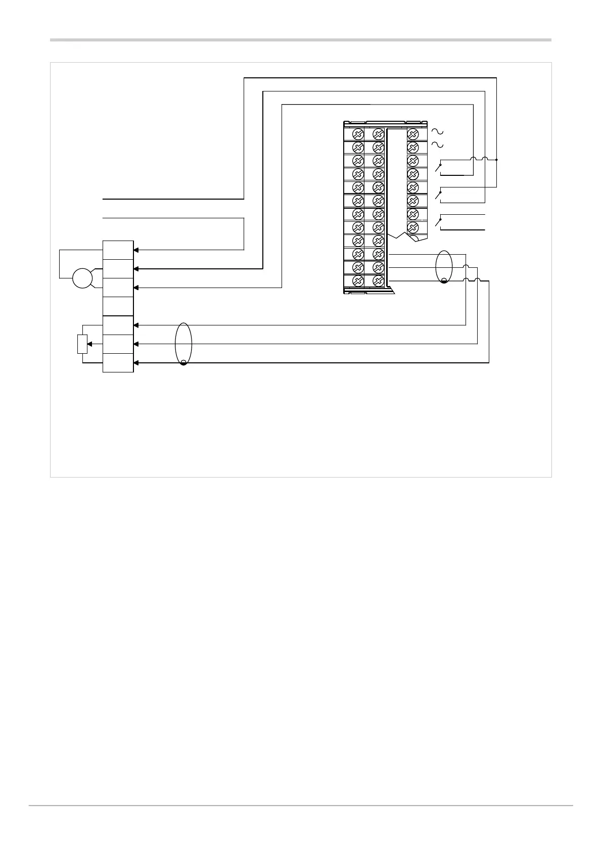
NOTE:
To enable the valve position control,
set parameter FUnC=VALV.P for the auxiliary input
The figure shows the valve feedback connection at the AUX1 input.
Alternatively, you may connect the valve feedback to the AUX2 input,
if present.
VALVE CONNECTION
Valve connection diagram
for models 1650V (or 1650PV)-X-RR...
for models 1850V (or 1850PV)-X-RR...
default OUT2 (OPEN), OUT3 (CLOSE)