32 ADL300 • Functions description and parameters list
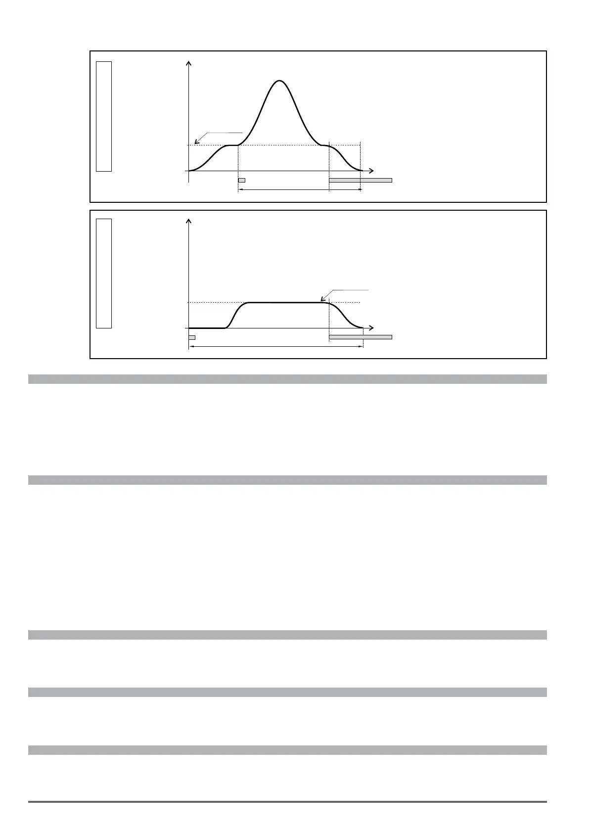
Case 2
Speed
Slow speed
Distance
Slow Down Land
Close to Slow Down
Case 3
Speed
Slow speed
Distance
Slow Down
Land
After Slow Down
Menu PAR Description UM Type FB BIT Def Min Max Acc Mod
5.5.13 11140 Delay acq time ms FLOAT 15 0.00 10.00 RW FVS
Setting of the delay time for sending the slow down signal.
The value of this parameter is used to compensate for the distance covered during the delay time between the passage
of the cabin on the slow down sensor and receipt of the decelerate command by the drive. At high speeds this distance
can have signicant values: e.g. with a cabin travelling at 2 m/s and a delay time of 30 ms, the distance covered and to be
taken into consideration during the deceleration phase is 6 cm.
Menu PAR Description UM Type FB BIT Def Min Max Acc Mod
5.5.14 11142 Calc space hi-speed UINT16 1 0 8 RW FVS
Setting of the high speed to be used to calculate distances.
0 Multispeed 0
1 Multispeed 1
2 Multispeed 2
3 Multispeed 3
4 Multispeed 4
5 Multispeed 5
6 Multispeed 6
7 Multispeed 7
8 Null
Menu PAR Description UM Type FB BIT Def Min Max Acc Mod
5.5.15 11276 Kp Landing Float 0.0000 0 100 RW FVS
Lets you congure proportional gain to control the landing curve.
Menu PAR Description UM Type FB BIT Def Min Max Acc Mod
5.5.16 12030 Acceleration space m FLOAT 0 R FVS
The distance necessary to accelerate from zero speed to the high speed selected in the previous parameter is displayed.
Menu PAR Description UM Type FB BIT Def Min Max Acc Mod
5.5.17 12032 Deceleration space m FLOAT 0 R FVS
The distance necessary to stop from the high speed is displayed.

 Loading...


