21
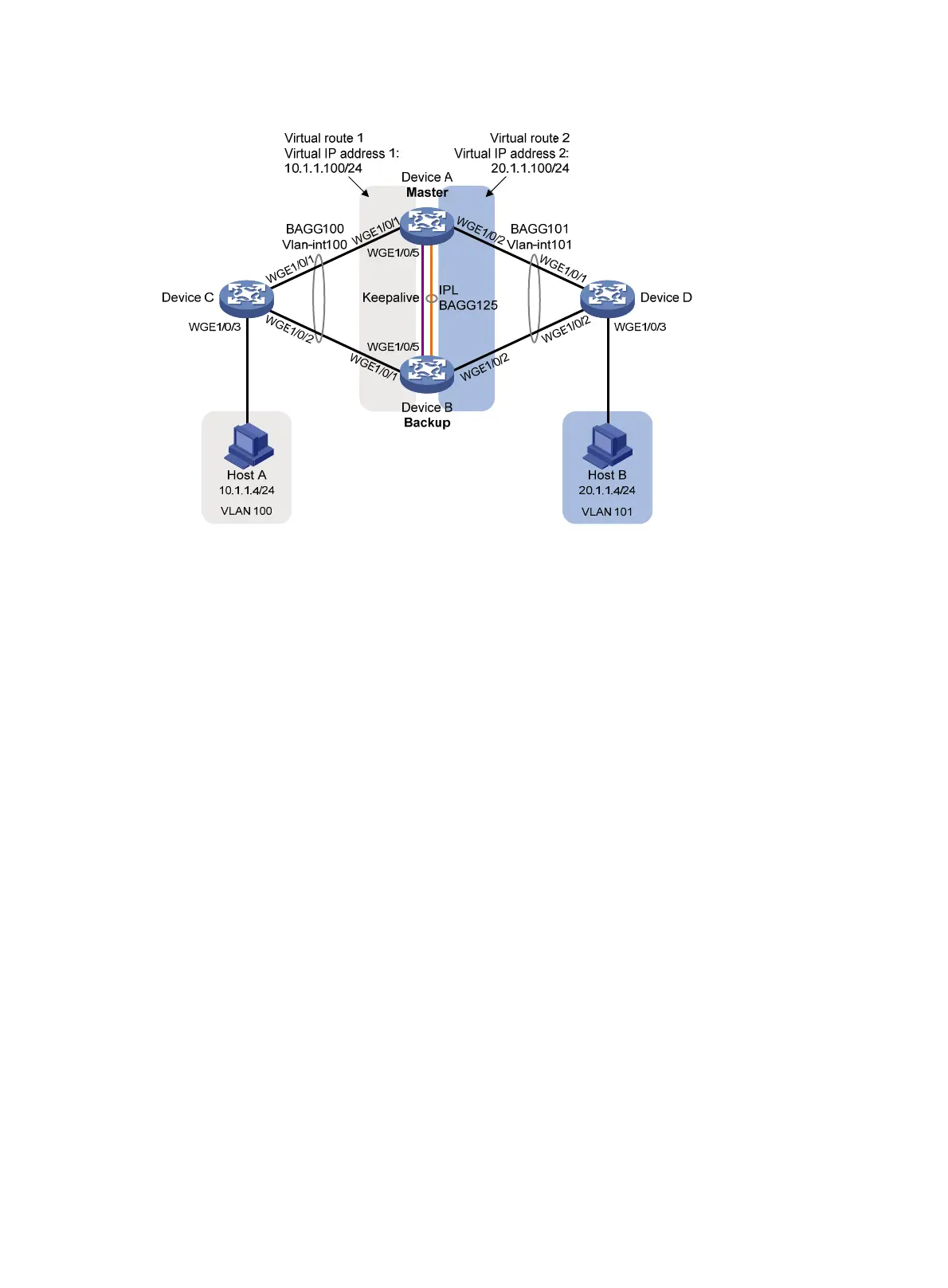
Figure 8 Network diagram
Procedure
1. Configure Device A:
# Configure DR system settings.
<DeviceA> system-view
[DeviceA] drni system-mac 1-1-1
[DeviceA] drni system-number 1
[DeviceA] drni system-priority 123
# Configure DR keepalive parameters.
[DeviceA] drni keepalive ip destination 1.1.1.2 source 1.1.1.1
# Set the link mode of Twenty-FiveGigE 1/0/5 to Layer 3, and assign the interface an IP address.
The IP address will be used as the source IP address of keepalive packets.
[DeviceA] interface twenty-fivegige 1/0/5
[DeviceA-Twenty-FiveGigE1/0/5] port link-mode route
[DeviceA-Twenty-FiveGigE1/0/5] ip address 1.1.1.1 24
[DeviceA-Twenty-FiveGigE1/0/5] quit
# Exclude the interface used for DR keepalive detection (Twenty-FiveGigE 1/0/5) from the
shutdown action by DRNI MAD.
[DeviceA] drni mad exclude interface twenty-fivegige 1/0/5
# Create Layer 2 dynamic aggregate interface Bridge-Aggregation 125, and specify it as the
IPP.
[DeviceA] interface bridge-aggregation 125
[DeviceA-Bridge-Aggregation125] link-aggregation mode dynamic
[DeviceA-Bridge-Aggregation125] port drni intra-portal-port 1
[DeviceA-Bridge-Aggregation125] quit
# Assign Twenty-FiveGigE 1/0/3 and Twenty-FiveGigE 1/0/4 to aggregation group 125.
[DeviceA] interface twenty-fivegige 1/0/3
[DeviceA-Twenty-FiveGigE1/0/3] port link-aggregation group 125

 Loading...


