Fault description Cause Remedy
Workpiece is not transported
e
venly through the machine
during thickness planing
Workpiece is not properly
positioned on the thicknessing
table
First machine the workpiece on the
planer unit
"Straight cut" at the beginning
of the w
orkpiece when thick-
ness planing
Insufficient spring pressure on
the infeed side feed roller
Contact Felder Group service
"Straight cut" at the end of
the w
orkpiece when thickness
planing
Insufficient spring pressure on
the outfeed side feed roller
Contact Felder Group service
"Oblique cut" at the beginning
of the w
orkpiece when thick-
ness planing
Insufficient spring pressure on
one side of the infeed side
feed roller
Contact Felder Group service
"Oblique cut" at the end of
the w
orkpiece when thickness
planing
Outfeed roller spring pressure
too low on one side
Contact Felder Group service
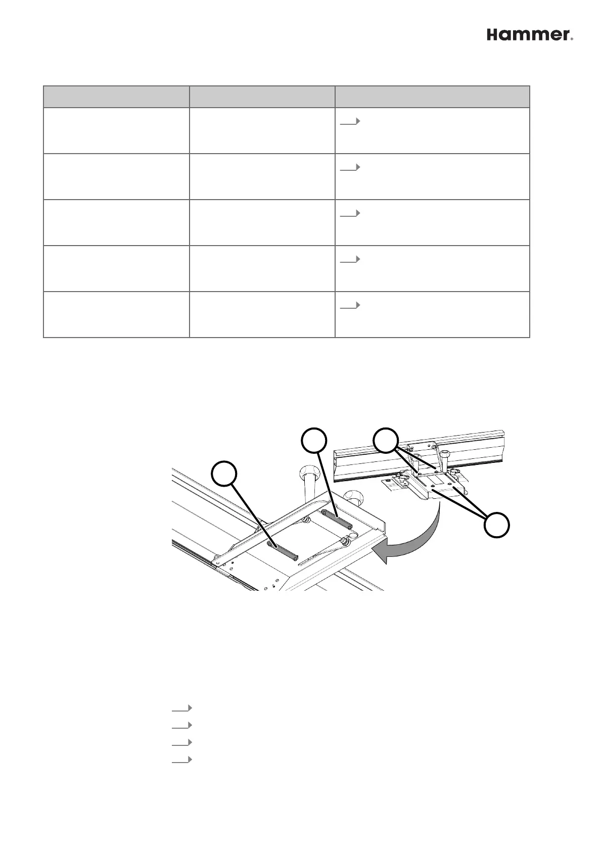
11.4 Correct the planing fence angle
An e
xact angle between the fence guide bar and planing table is very important
when planing the narrow edge and chamfering.
The 0° and 45° position are ensured by stop bars on the underside of the fence.
Fig. 59: Planing fence - angle correction
1 front stop bar (0° angle)
2 rear stop bar (45° angle)
3 Clamping screws (0° angle)
4 Clamping screws (45° angle)
Tool:
● Hex key
1.
Switch off the machine and secure it against being switched on again.
2.
Loosen the clamping screws of the required stop bar.
3.
Set the 0° and the 45° angle by moving the stop bar.
4.
Tighten clamping screws.