ACO6800+ Installation and Operation Manual 37
Copyright © 2009, Harris Corporation
Chapter 4: ACO6800+ISD Parameters, LEDs, and Alarms
Group A Switch Low
Priority
1, C Sets the low priority for switching
• GPI Input
•Manual
• Alarms
Group A Alarms Switch
Level
1, D Sets the level for alarm auto switch 1 to 10 (6)
Group A Manual Switch 1, E Sets what the output source will be
when a channel is switched manually
• Disable
• Switch to A1
• Switch to A2
Group A Relay Bypass 1, 1 Activates the relay bypass
•On
• Off
Group A Relay Status
[RO]
Displays whether or not the relay is
active
•On
•Off
ACO Group A > General Purpose Interface
Group A GPI In Trigger
Level
1, 2 Sets the level at which an alarm is
triggered for the Group A GPI Input
• Active Low
• Active High
Group A GPI Out
Trigger Level
1, 3 Sets the level at which an alarm is
triggered for the Group A GPI Output
• Active Low
• Active High
Group A GPI Input_1
[RO]
Displays whether or not GPI Input_1
has been switched to A1
•N/A
• Switch to A1
Group A GPI Input_2
[RO]
Displays whether or not GPI Input_2
has been switched to A2
•N/A
• Switch to A2
Group A GPI Input_3
[RO]
Displays whether or not GPI Input_3
has been switched to Relay Bypass
•N/A
• Relay Bypass
Group A GPI Output_1
[RO]
Displays whether or not A1 is
selected as current output source
•N/A
• Input A1
online
Group A GPI Output_2
[RO]
Displays whether or not A2 is
selected as current output source
•N/A
• Input A2
online
Group A GPI Output_3
[RO]
Displays whether or not the relay
bypass has been activated
•N/A
• Signal Bypass
ACO Group A > MISC Settings
OutA OSD Enable 1, 4 Enables the on-screen display
Note This parameter is not present in
ASI mode.
• Off
•On
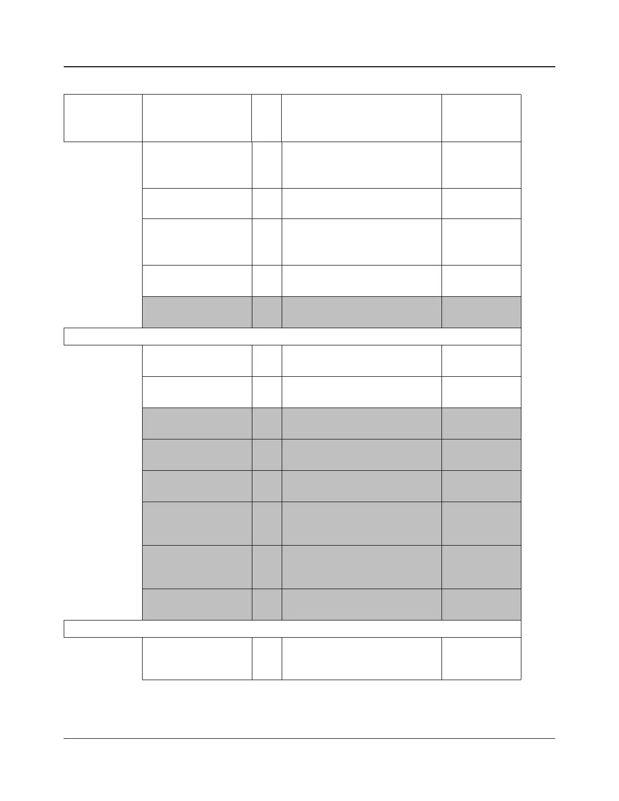
Table 4-1. ACO6800+ISD Parameters (Continued)
Group Parameter Name
Bank,
Switch
Function Options