COMPUSHIFT II Manual – COMPUSHIFT II Manual
Additional Guides & Information– 91
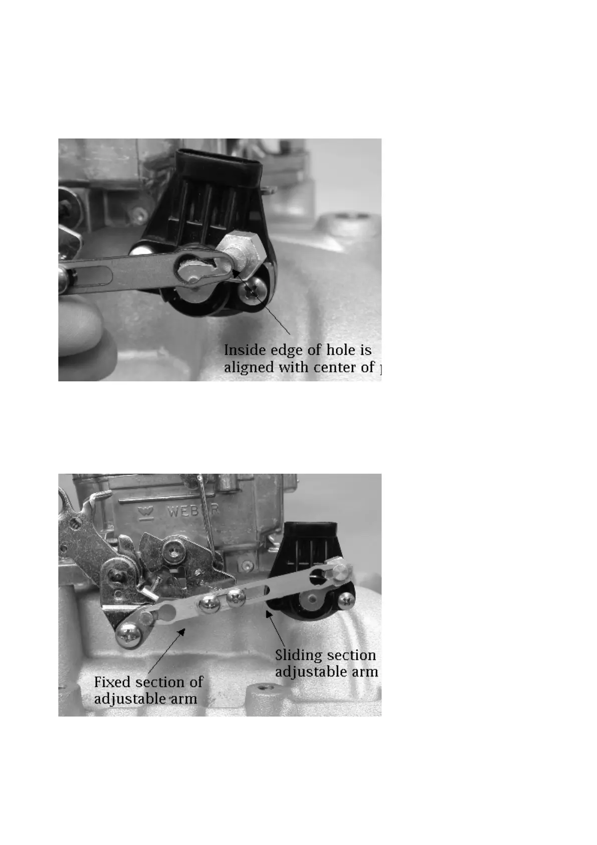
7.5.12 Installing the Adjustable Arm
The adjustable arm is made of two pieces: the fixed, threaded section and the sliding section. Identify and assemble
the adjustable arm, leaving the screws gently snug. Attach the fixed section of the adjustable arm to the ratio arm.
The screw heads should face outward, away from the carburetor.
Adjust the arm length so that edge of the hole of the sliding section is aligned with the center of the throttle position
sensor pin. The correct length is shown in the picture above. Tighten the adjustable arm screws at this position.
Disable the fast idle cam for the choke so that the carburetor butterflies are on low speed idle.