COMPUSHIFT II Manual – COMPUSHIFT II Manual
Specifications & Pinouts– 98
•
•
•
•
•
•
•
•
•
•
•
•
•
•
•
•
•
•
•
•
•
•
•
•
•
•
•
Automatic calibration to stroke range
5 volt reference signal provided
Dual CAN buses for connection to vehicle networking
8.2.1.7 Connectors
Power – connection to vehicle power
Engine – connection to throttle position sensor, tachometer, speedometer, MAP sensor
Options – connection to display and accessory switches and indicators
Trans A – connection to transmission
Trans B – connection to transmission and optional hydraulic pressure sensor
USB – connection to PC
8.2.1.8 Indicators
1 Red/Green LED indicating system status
8.3 Display Specifications
8.3.1 COMPUSHIFT II
8.3.1.1 Type
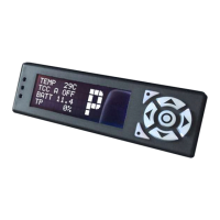
Handheld or dash-mountable backlit LCD display with 7-key keypad
8.3.1.2 Display Characteristics
Number of Characters
80 (20 characters x 4 lines)
Matrix format
5″ x 7″ with underline
Display Area
82.00 mm x 28.40 mm
Character Size
3.90 mm x 5.20mm (not including underline)
LED Backlight
100,000 hours typical life
Three-color adjustable brightness
8.3.1.3 Chassis
Chassis is a factory-sealed, injection molded with a threaded inserts for mounting. There are no user-
serviceable parts inside. The chassis should not be opened.
Dimensions
7.125″ x 2.00″ x 1.5″
Threaded Mounting Insert
4-40 machine screw