158
11.1 Connecting the D/A Output Terminal
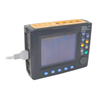
Insert the 9441 CONNECTION CABLE into
the D/A output terminal, aligning the connec-
tor guide grooves (the connector is
equipped with a lock). When removing the
connection cable, hold it by its plastic part.
Connection to the D/A Output Terminal
9441 CONNECTION CABLE
Pin No. Signal Name 9441 Cable Color
1 D/A output ch1 Red
2 D/A output ch2 White
3 D/A output ch3 Black
4 D/A output ch4 Yellow
5 Ground Blue
6 Ground Green
7 Ground Brown
8 Ground Gray
D/A output connector
(D/A OUT)
• Pins 5 to 8 are common ground pins.
• A plastic connector is used for the connection cable. To pre-
vent damage to the connector, do not insert it into the terminal
without aligning the guide grooves, and do not pull it without
releasing the lock.
• The output resistance of the output terminal is approximately
100
Ω
. Make sure a recorder or other device to be connected
to the terminal has an input resistance of 100 k
Ω
or more.

 Loading...