112
_____________________________________________________________________________________________
8.2 Communication
______________________________________________________________________________________________
Bit 7
Not used
Bit 6
MSS
MSS shows the logical sum of other bits in the status byte register.
Bit 5
ESB
Standard event summary (logical sum) bit
ESB shows the logical sum of the standard event status register.
Bit 4
MAV
Message available
MAV indicates the output queue has messages.
Bit 3
Not used
Bit 2
Not used
Bit 1
Not used
Bit 0
ESB0
Event summary (logical sum) bit 0
ESB0 shows the logical sum of the event status register 0.
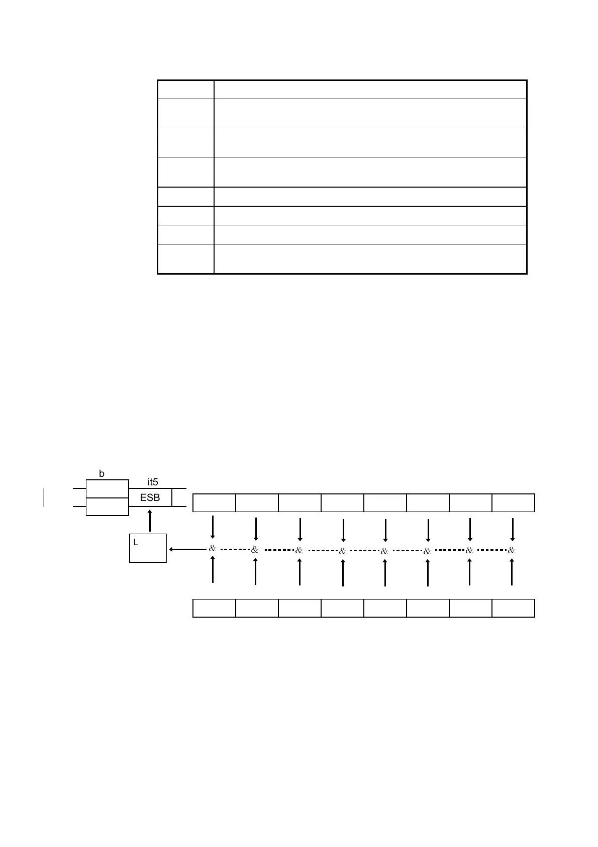
bit7 bit6 bit5 bit4 bit3 bit2 bit1 bit0
PON URQ CME EXE DDE QYE RQC OPC
Standard event status re
isters
SESR
bit7 bit6 bit5 bit4 bit3 bit2 bit1 bit0
PON URQ CME EXE DDE QYE RQC OPC
Standard event status enable re
isters
SESER
&
Logical
sum
&
& &
&&&
&
bit5
ESB
bit6
RQS
MSS
Although the MSS bit is read out on an "∗STB?" query, on a "∗CLS"
command for example it is not cleared until the event is cleared.
(2) Service request enable register (SRER)
This register masks the status byte register. Setting a bit of this register to 1
enables the corresponding bit of the status byte register to be used.
Event Registers
(1) Standard event status register (SESR)
The standard event status register is an 8-bit register. If any bit in the
standard event status register is set to 1 (after masking by the standard event
status enable register), bit 5 (ESB) of the status byte register is set to 1.
The standard event status register is cleared in the following four situations:
① When a "∗CLS" command is received.
② When an "∗ESR?" query is received.
③ When the unit is powered on.
④ When the I/F is Switched.