3
────────────────────────────────────────────────────
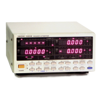
1.3 Identification of Controls and Indicators
────────────────────────────────────────────────────
1
2
3
4
5
6
7
8
9
10
11
12
13
14
A
Display b
Voltage range Display d
Condition of integration,
hold, settings
Display a
Display c
Rectifier
type
Response
speed
Power
switch
Current range
See Section 1.4
Comparator display
Front Panel
Current input terminal Voltage input terminal AC inlet (Power supply connector)
RS-232C interface GP-IB interface
Connector for external control and output
Rear Panel
1.3 Identification of Controls and Indicators

 Loading...