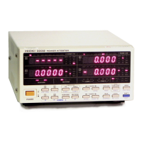
23
────────────────────────────────────────────────────
3.3 Selecting the Display
────────────────────────────────────────────────────
1
2
3
4
5
6
7
8
9
10
11
12
13
14
A
d
a
Display
Function
a V, A, W, VA, var, PF, Hz, TIME
b V, A, W, Ip, Ah, +Wh, ±Wh
c V, A, W, VA, var, PF, ○, Ip, Hz, Ah, +Wh, -Wh, ±Wh, TIME
d V, A, W, VA, var, PF, ○, Ip, Hz, Ah, +Wh, -Wh, ±Wh, TIME
b
c
V
Voltage
A
Current
W
Active power
VA
Apparent power
var
Reactive power
PF
Power factor
○
Phase angle
Ip
Current peak
Hz
Frequency
Ah
Integration current
+Wh
Positive integration power
-Wh
Negative integration power
±Wh
Total integration power
TIME
Integration elapsed time
NOTE
3.3 Selecting the Display
Press the following keys, the function can be selected on each display.
The voltage, current, and effective power channels display up to 130% of
range. Values in excess of that amount will result in display of "o.r.",
indicating out of range. The display will show o.r. for the results of
calculations made using data that is out of range.
During comparator display, the channel number and table number for the
comparator is displayed on the Display c screen for 1 second by pressing the
a
,
b
,or
d
key.
Pressing the
CH
key returns to the normal display screen. (For comparator
display, see Section 4.11)

 Loading...