A11
Zero Adjustment
When performing zero adjustment using the zero adjustment board of an accessory:
When performing zero adjustment, you must not use a metal plate in substitution for the attached zero
adjustment board. The zero adjustment board is structured to connect between the SENSE terminals and the
SOURCE terminals with one point. When performing zero adjustment of the optional L2002 Clip Type Probe
and the L2003 Pin Type Probe, the zero adjustment board is used.
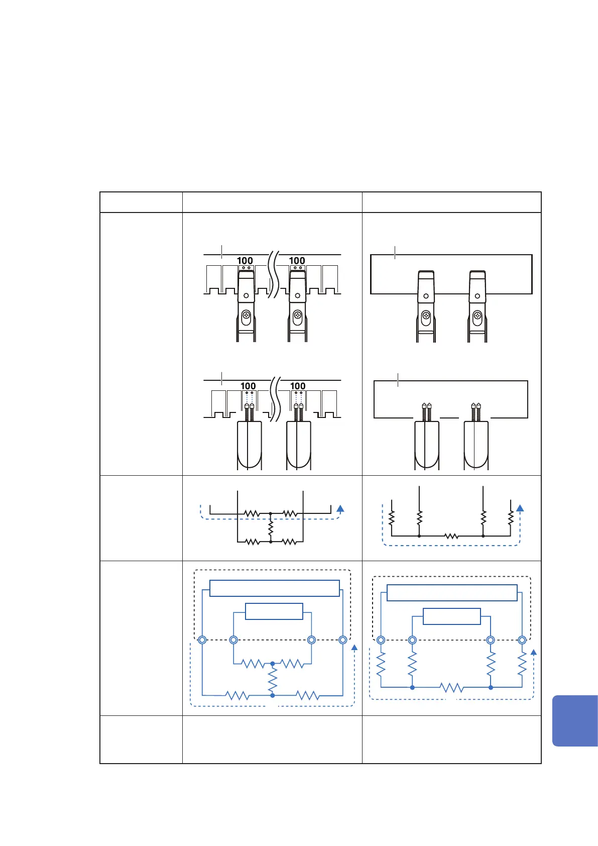
The equivalent circuits when connecting to the zero adjustment board and to a metal plate are shown in Table.
Connection method when performing zero adjustment. When connecting using the zero adjustment board, the
connection is the same as shown in the Connection Method table (a). Thus, the voltage between SENSE-H
and SENSE-L becomes 0 V. However, when connected using metal, the connection is the same as shown in
the Connection Method table (b). The voltage between SENSE-H and SENSE-L is thus not 0 V.
(a) (b)
Connection method
L2002
Zero adjustment board
L2003
Zero adjustment board
L2002
Metallic plate
L2003
Metallic plate
Equivalent circuit
R
SOL
R
SEH
R
SOH
R
SEL
R
Short
I
SOURCE-H
SENSE-H SENSE-L
SOURCE-L
R
SOL
R
SEH
R
SOH
R
SEL
R
Short
I
SOURCE-H
SENSE-H SENSE-L
SOURCE-L
Detailed equivalent
circuit
R
SEH
R
SOH
R
SOL
R
SEL
R
Short
I
Constant-current power supply
Voltmeter
SOURCE-H
SENSE-H SENSE-L
SOURCE-L
R
SEH
R
SOH
R
SOL
R
SEL
R
Short
I
Constant-current power supply
Voltmeter
SOURCE-H
SENSE-H SENSE-L
SOURCE-L
As the connection
method when
performing the zero
adjustment
Correct
Incorrect
10
9
8
7
6
5
4
3
2
1
Appx. Ind.
 Loading...