31
Checking the Measurement Results
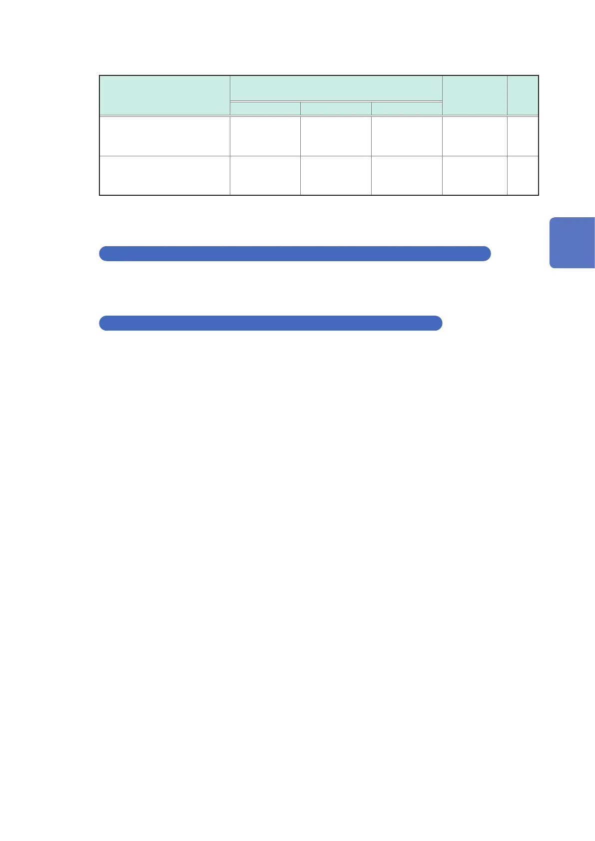
The guide line in the abnormality detection of the measurement current
Place for abnormality
detection
Target resistance value for abnormality
detection
Measurement
abnormality
type
Indi-
cation
3 m
Ω
range 10 m
Ω
range 100 m
Ω
range
SOURCE-H 1.5
Ω
to 4.0
Ω
5
Ω
to 12
Ω
50
Ω
to 55
Ω
Measurement
current
abnormality
------
SOURCE-L 1.5
Ω
4
Ω
45
Ω
Measurement
current
abnormality
------
The resistance values indicate the guideline, which are not strictly dened. The detected value of
SOURCE-H changes based on the voltage of the measuring object.
Impedance measurement error due to voltage drift (Indication: VOLTAGE DRIFT)
The voltage of the measuring object considerably uctuates during the measurement.
When the difference between voltage values at the start and at the end of measurement is 10 mV
or more, the difference is detected as an error.
Return cable unconnected error (Indication: RETURN CABLE ERROR)
The probe’s return cable is not properly connected. It may be disconnected or the wire connection
may be wrong.
To reduce noise due to the electromagnetic induction, it needs the return cable where the current
ows opposed to the measurement current. The return cable has a structure that short-circuits
between the shield wire of the SOURCE-H and the shield wire of the SOURCE-L. (In the optional
probe, the return cable short-circuits between the shield wire of the SOURCE-H and the shield wire
of the SOURCE-L.)
3
Basic Measurement