30
Checking the Measurement Results
3.6 Checking the Measurement Results
Detecting the measurement abnormality
When the measurement is not normally performed, the indication expressing the measurement
abnormality appears on the screen, and the ERR signal from the EXT.I/O is output.
Contact error
When the resistance value is greater between SOURCE-H and SENSE-H, or between SENSE-L
and SOURCE-L, the contact error appears. The possible causes are listed below.
• The measurement probe is not connected to the measuring object.
• The probe is broken.
• The contact resistance or the wiring resistance are large due to frictional wear and dirt of the probe.
• The circuit protection fuse is broken.
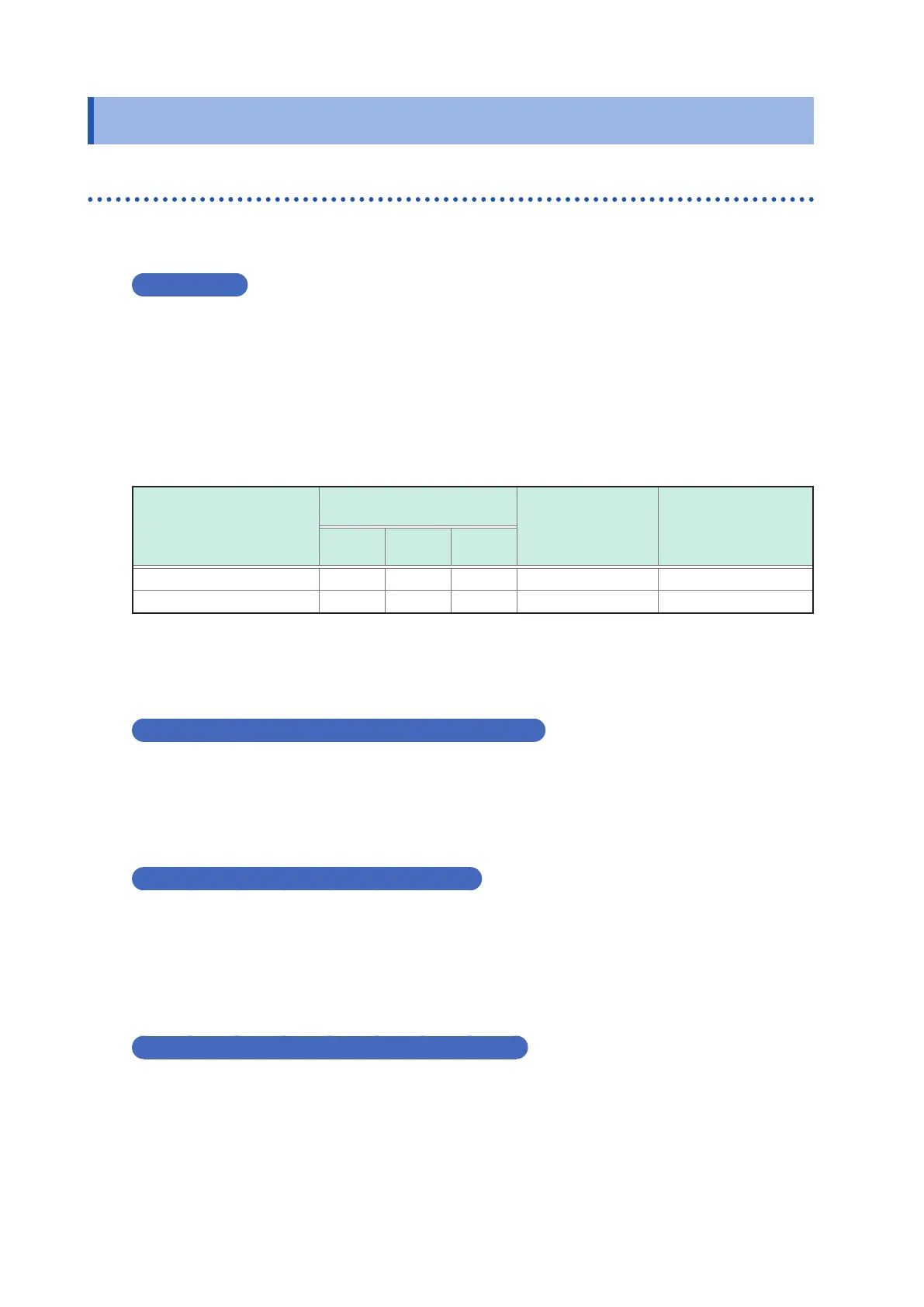
The guideline in the contact error detection
Place for abnormality
detection
Target resistance value for
abnormality detection
Measurement
abnormality type
Error indication
3 m
Ω
range
10 m
Ω
range
100 m
Ω
range
SOURCE-H and SENSE-H 10
Ω
15
Ω
50
Ω
H Contact error
CONTACT ERROR H
SOURCE-H and SOURCE-L 10
Ω
15
Ω
50
Ω
L Contact error CONTACT ERROR L
• The resistance values indicate the guideline, which are not strictly dened.
• The capacitance of the measurement probe is greater than 20 nF, the measurement abnormality may not
be detected.
• For functions V and T, target resistance value for abnormality detection will be the same resistance value
as 100 m
Ω
range.
Over-voltage input error (indication: OVER VOLTAGE)
When the voltage of the measuring object exceeds the measurable range, OVER VOLTAGE
appears.
The measurable voltage range is -5.10000 V to 5.10000 V.
It may be displayed SENSE-H and SOURCE-H short-circuit, and SENSE-L and SOURCE-L short-
circuit state.
Voltage limit error (Indication: OVER V LIMIT)
When the voltage of the measuring object exceeds the voltage limit setting range, LIMIT VOLTAGE
appears.
For the setting method of the voltage limit, refer to “4.6 Preventing the Overcharge due to
Measurement Signal (Voltage Limit Function)” (p. 45).
It may be displayed SENSE-H and SOURCE-H short-circuit, and SENSE-L and SOURCE-L short-
circuit state.
Measurement current abnormality (Indication: ------)
This indication appears when the measurement current does not ow normally. The possible
causes are listed below.
• The contact resistance or the wiring resistance are large due to frictional wear and dirt of the
probe.
• The resistance of the measuring object is remarkably large to the range (Example: when 1 k
Ω
is
selected).
• When wiring is wrongly connected to a battery.
• When wiring is connected to a battery that is grounded.