29
Performing the Zero Adjustment
When measuring while changing the measurement range
If measured as below, zero adjustment will not be necessary every time the range is changed.
1. Perform zero adjustment at 3 m
Ω
range.
2. Save the current condition by panel saving function (p. 58).
(Zero adjustment data of the current range will be saved.)
3. Change the range to 10 m
Ω
and perform zero adjustment.
4. Save the current condition by panel saving function (p. 58).
5. Change the range to 100 m
Ω
and perform zero adjustment.
6. Save the current condition by panel saving function (p. 58).
7. Read the condition of the range used by panel saving function (p. 58), and then measure.
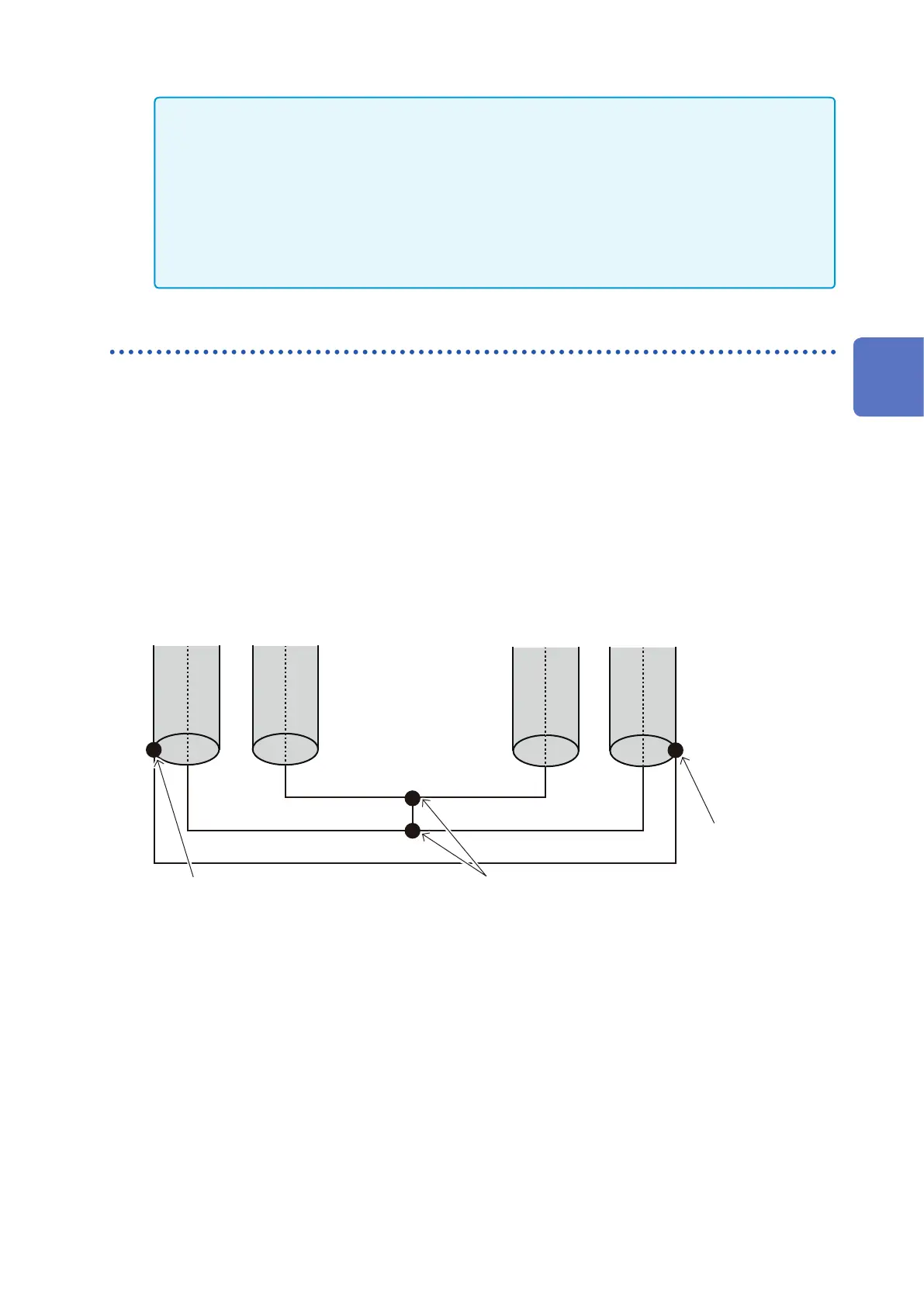
Connection when performing the zero adjustment
If the zero adjustment board is used, the connection will be as below.
Perform zero adjustment with the same connection when making your own measurement probe (refer to
“Appx. 3 Cautions When Making Your Own Measurement Probe” (p. A4)).
1
Connect the shields of SOURCE-H and SOURCE-L.
(Connected by the return cable)
2
Connect SENSE-H and SENSE-L.
3
Connect SOURCE-H and SOURCE-L.
4
Connect the above
2
and
3
lines at one point.
SENSE-HSENSE-L SOURCE-HSOURCE-L
Connection to the SOURCE shield Connect the above 2 and 3 at one point.
Connection to the
SOURCE shield
3
Basic Measurement