Appx.1
Appendix
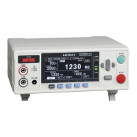
Appx. 1 Block Diagram
A
High Voltage Output
Discharge circuit
Voltage monitor
Contact check
Current
detection part
ADC
B
C
D
E
EUT
G
Switching
power
supply
EXT.I/O
CPU
RS-232C
Analog
output
F
Measurement block Control block
Analog Power
Output Trance
• With our unique technology, the ripple component in the DC voltage is reduced and DC
voltage is output without overshoot. The DC voltage can be changed between 25 V and 1000
V in increments of 1 V resolution. (A)
• In order to conform to safety standard IEC61010, the short circuit current is controlled under 2.0
mA. (B)
• Any charge in the equipment to be measured can be released quickly. (C)
• The voltage monitor is operating any time in addition to during tests, the voltage between
measurement terminals can always be monitored. (D)
• As a contact check circuit is installed and contacts are always monitored, the quality of an
insulation resistance test can be improved. (E)
• An operational isolation structure of 1000 V DC with sufcient isolation performance is
provided for the analog and digital units. (F)
• The auto-ranging 100-to-240 V switching power supply can provide stable measurements
even in poor power quality environments. (G)
Appendix
10
9
8
7
6
5
4
3
2
1
Appx. Ind.

 Loading...