EasyManua.ls Logo

Hitachi 65 - Installing and Removing Components

Hitachi 65
281 pages
Print Icon
To Next Page IconTo Next Page
To Previous Page IconTo Previous Page
Loading...
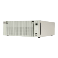
6. CHECKUP AND MAINTENANCE
6-5
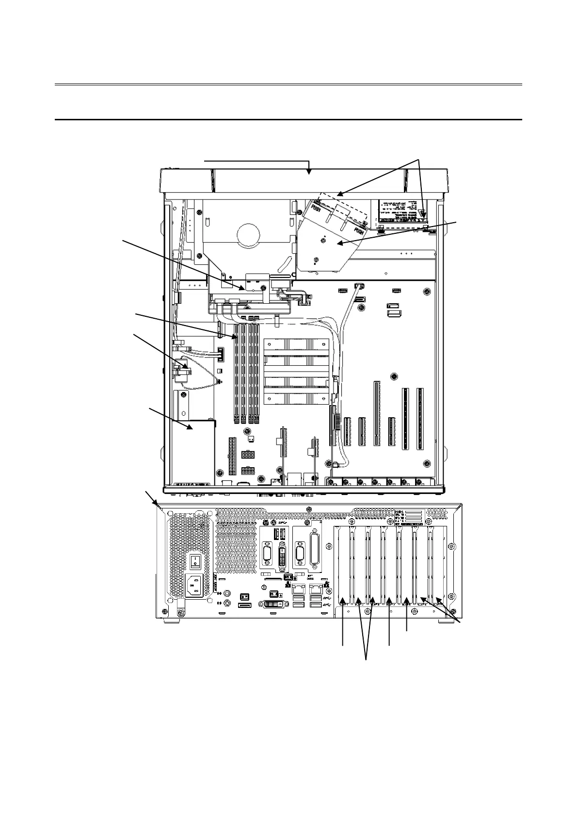
6.3 Installing and Removing Components
6.3.1 Types and locations of installed components
The figure below shows the types and locations of the components installed in this equipment.
(*1) This slot cannot be used because the RAID board is installed.
(*2) The internal connection is PCI Express x4, but the connector shape is PCI Express x8.
(*3) The internal connection is PCI Express x1, but the connector shape is PCI Express x4.
Figure 6-1 Types and Locations of Installed Components
Power Supply Unit
The cover of the
equipment
Dust filter
Lithium battery
Main memory slot
(from right to left,
A1 and A2 and B1
and B2)
DVD drive
HDD
Fan duct
Slot 2, 3(PCI Express x4)
Slot 4(PCI Express x16)
Slot 6, 7(PCI)
Front fan
Slot 1(PCI Express x4)
(*1)(*2)
A2
B2
Slot 5(PCI Express x1) (*3)

Table of Contents

Related product manuals