6. CHECKUP AND MAINTENANCE
6-14
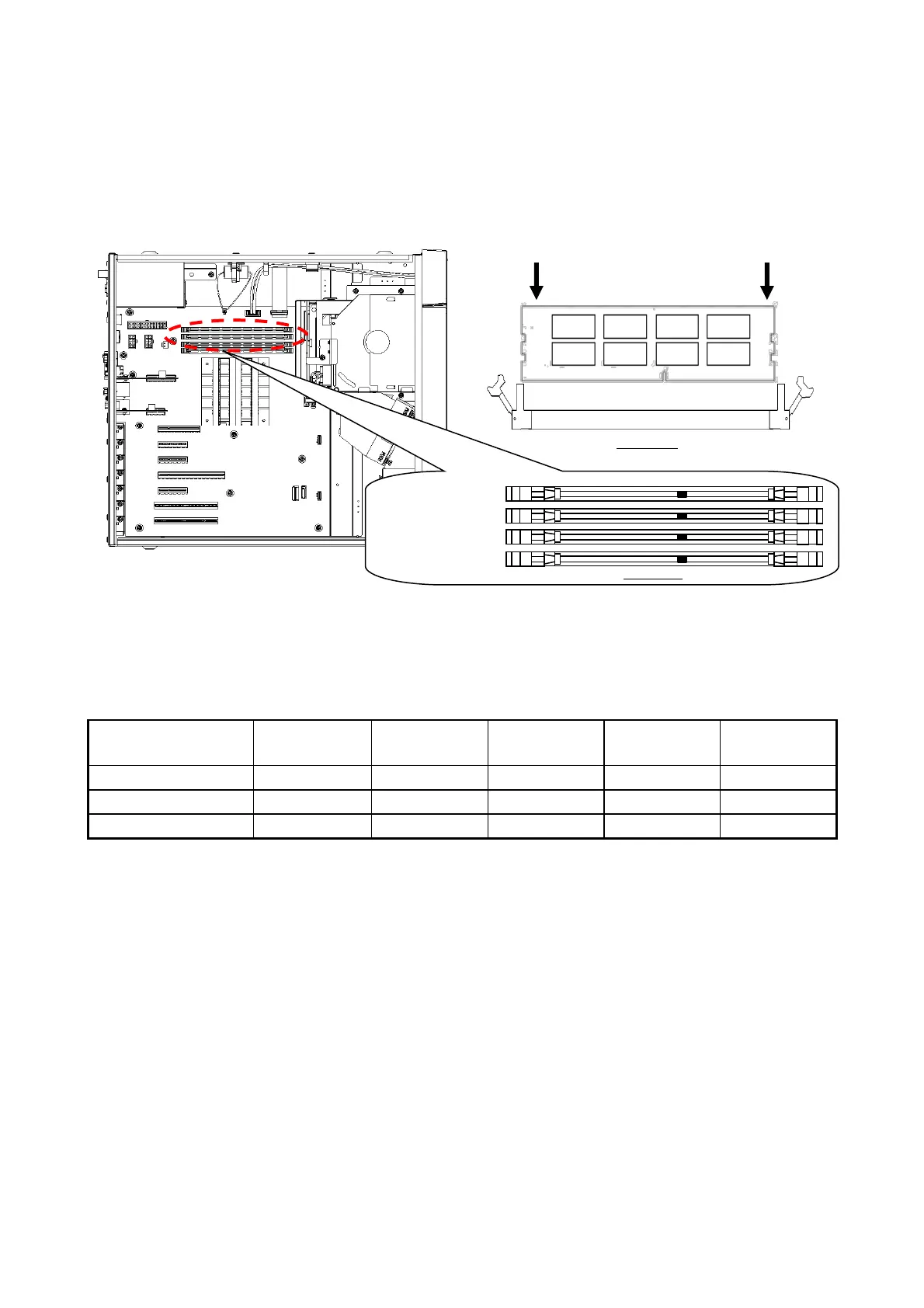
[3] Make sure the lock on both ends of the connector of the memory slot is open.
[4] Insert the main memory into the connector from directly above the connector.
When the main memory is inserted, you will hear a click and it is locked. Make sure the
lock is completely closed.
Figure 6-5 Installing a main memory
On this equipment, only the following combinations are allowed.
Table 6-3 Main memory combination list
(3) Removing main memory
Follow the procedure described in “(2) Installing a main memory” in reverse to remove main
memory. Also, be careful when opening locks at both ends of the connector of the memory slot
at the same time, a main memory will be disconnected from the memory slot.
(4) Reconfiguring the memory dump file settings
When you change the capacity of main memory, you must reconfigure the memory dump
collection settings.
When you reconfigure the memory dump collection setting, see “8.2.1 Memory Dump
Confirmation Message” for details.