6. CHECKUP AND MAINTENANCE
6-13
(2) Installing a main memory
⚫ The orientation of a main memory module on a connector is fixed. When you
install a main memory module, make sure the orientation is correct.
Otherwise, failure of the equipment may result.
⚫ Do not install main memory modules with different capacities in slot A1 and slot
B1, or in slot A2 and slot B2. If you do, the modules may not be recognized.
[1] Follow the instructions in “6.3.3 Installing and removing the cover of the equipment” to
remove the cover of the equipment.
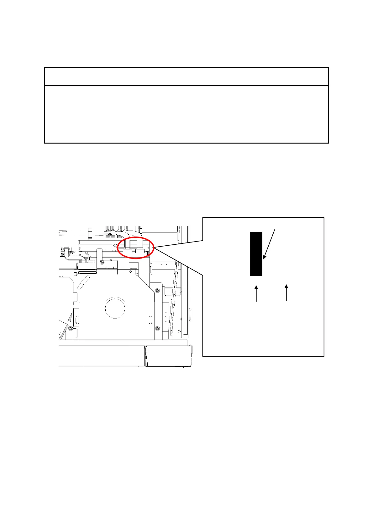
[2] Refer to the figure below and remove the SATA cables from the backboard connectors.
Figure 6-4 Removing the SATA cables
Note: When installing the SATA cables,
check the silk printing on the
cables and attach them to the
corresponding connectors.