52
4.3.4. Output Function
Monitor the states of the IJ Printer by connecting the print output (print-in-progress or print-complete), online
output, ready, fault, and warning signals to the pin numbers 10 to 23 on the terminal blocks TB1 and TB2.
Monitor the ready, fault, and warning output signals by connecting no-contact (transistor) output or contact
(relay) output to the pin numbers 1 to 9 on the terminal block TB5 *TB5 is optional parts.
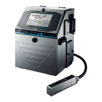
● Internal circuit diagram
(a) Output via the NPN interface (no-voltage input)
● The output transistor is an open collector and uses the logic to turn the transistor on at operation
ON.
● In the external unit, use a voltage and current that meet the specifications below.
– IL ≤ 20 mA (VCE: TYP0.6 V, MAX.2 V)
– Vd ≤ 30 VDC
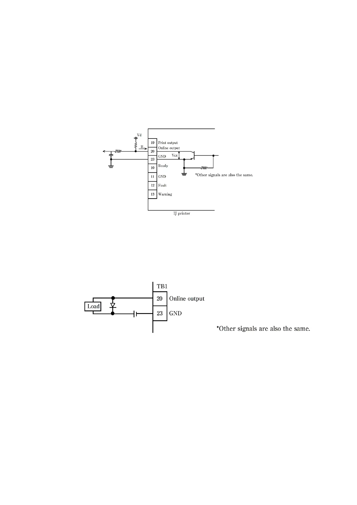
● Wiring precautions
● When a load is an inductive charge such as a relay or solenoid, connect a counter electromotive
force diode in parallel with the load.
● The load circuit is for DC only. It is not used for AC load.

 Loading...