Home
Hologic
Medical Equipment
Affirm
Service Manual
Page 77 (Appendix A System Specifications)
Hologic Affirm - Appendix A System Specifications; Affirm System Measurements; Figure 41: Affirm Biopsy Guidance Module
116 pages
Manual
Save Page as PDF
To Next Page
To Next Page
To Previous Page
To Previous Page
Loading...
Affi
rm Breast
Biopsy
Guidance Sy
stem Service
Manual
Ap
pend
ix A
:
System
Specif
ications
MAN
-
0575
4 Rev
ision 00
2
Page 65
Appendix A
S
yste
m Sp
ecif
icatio
ns
A.1
Affirm System
M
easureme
nts
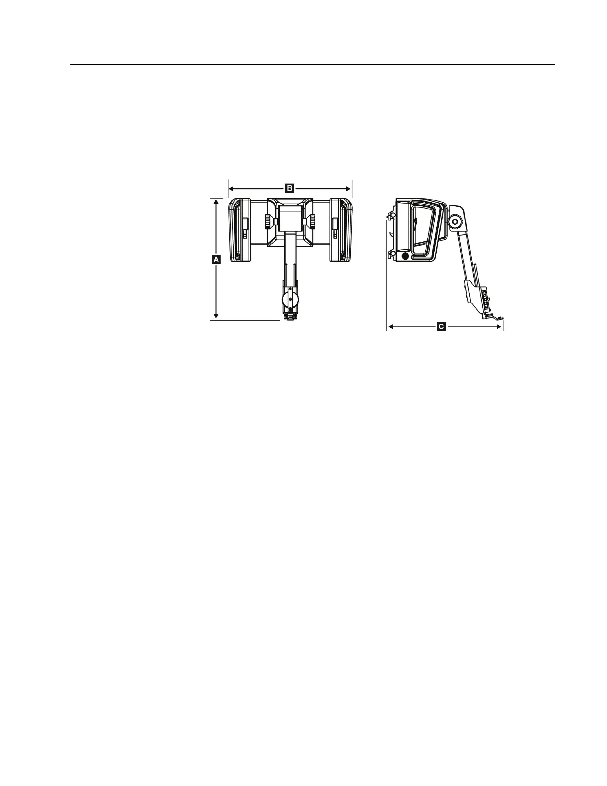
Figur
e 44:
Affirm Biop
sy Guidance
Module
A. Height
37.1 cm
(14
.6 inches
)
B.
Wid
th
37.8 cm
(14
.9 inches
)
C. Depth
35.6 cm
(14
inches)
Weight
6.8 k
g (15
pounds)
Appendi
x
A
76
78
Table of Contents
Main Page
Table of Contents
5
List of Figures
9
List of Tables
11
1: Introduction
13
Intended Use
13
User Profiles
13
Mammography Technologist
13
Radiologists, Surgeons
13
Medical Physicist
14
Training Requirements
14
Quality Control Requirements
14
Where to Find Technical Description Information
14
Warranty Statement
15
Technical Support
15
Product Complaints
15
Hologic Cybersecurity Statement
15
Symbols
16
Descriptions of Warnings, Cautions, and Notes
17
2: General Information
19
System Overview
19
Figure 1: Affirm Biopsy System on the Selenia Dimensions Mammography System
19
How to Handle the Biopsy Guidance Module
20
Figure 2: How to Lift the Biopsy Guidance Module
20
Figure 3: How to Store the Biopsy Guidance Module
20
Safety Information
21
Warnings and Precautions
21
Compliance
22
Compliance Requirements
22
Label Locations
23
Figure 4: Biopsy Guidance Module Label Location
23
Figure 5: Lateral Arm Serial Number Label Location
23
3: Installation, Verification, and Removal
25
Add Licensed Features
25
Unpacking
28
Preinstallation Check
28
Figure 6: Affirm System Icon Location
28
Biopsy Guidance Module Components
29
Figure 7: Biopsy Guidance Module
29
Biopsy Control Module Components
30
Table 1: Components of the Biopsy Guidance Module
30
Figure 8: Biopsy Control Module
31
Table 2: Components of the Biopsy Control Module
31
Installation of the Main Components
32
Install the Internal Gantry Biopsy Guidance Module Cables
32
Figure 9: Gantry/Biopsy Guidance Module Cables
32
Attach the Biopsy Guidance Module
33
Figure 10: Installation of the Biopsy Guidance Module
33
Attach the Biopsy Control Module
34
Figure 11: Attachment of the Biopsy Control Module
34
System Verifications
35
Confirm the Host Connection
36
Figure 12: Home Screen
36
Figure 13: Service Screen
36
Verify in Caltool
37
Installation and Removal of Accessories
37
Tabletop Stand for Affirm System
37
Biopsy Compression Paddles
38
Needle Guide
38
Figure 14: Installation of the Needle Guide Holder on the Standard Device Mount
39
Figure 15: Installation of the Needle Guide on the Standard Needle Guide Holder
39
Biopsy Device Adapter
40
Biopsy Device
40
Figure 16: Attaching a Biopsy Device Adapter to Device Mount (Standard)
40
Lateral Arm and Lateral Arm Accessories
41
Figure 17: Lateral Arm Components
41
Table 3: Components of the Lateral Arm
41
Figure 18: Left Needle Approach of Lateral Arm (Blue)
43
Figure 19: Right Needle Approach of Lateral Arm (Yellow)
43
Figure 20: Installing Lateral Arm Stand over Image Receptor
44
Figure 21: Removing the Needle Guide Holder from the Standard Device Mount
45
Figure 22: Installing Lateral Arm to Device Mount
46
Figure 23: Lateral Arm Mounting Side Selection Screen
47
Figure 24: Attaching Blue Needle Guide Holder to Needle Guide Rods (Left Needle Approach)
48
Figure 25: Attaching Yellow Needle Guide Holder to Needle Guide Rods (Right Needle Approach)
48
Figure 26: Installing Disposable Needle Guide on Needle Guide Holder (Lateral Arm)
49
Figure 27: Carriage Lever Locked and Unlocked Positions
49
Figure 28: Locked and Unlocked Positions of Device Mount Lever
50
Figure 29: Installing Device Mount Onto Lateral Arm Carriage
50
Figure 30: Lock Levers in Fully Locked Position
51
Figure 31: Scales and Positioning for X-Stop and Carriage
52
Figure 32: Installing X-Stop on Lateral Arm
53
Removal of the Main Components
54
Biopsy Control Module
54
Biopsy Guidance Module
54
Tabletop Stand for the Affirm System
55
Storage Case for the Lateral Arm
55
Figure 33: Affirm System Tabletop Stand
55
Figure 34: Lateral Arm and Storage Case
56
4: Calibration Procedures
57
Required Tools and Equipment
57
Front Needle Guide Alignment
58
Alignment for Standard Approach
59
Alignment for Lateral Approach
59
Biopsy Guidance Hardware
60
Geometry Calibration
60
STX Calibration
61
STX Calibration for Standard Approach
61
Table 4: Calibration Target List
62
STX Calibration for Lateral Approach
63
Table 5: Lateral Arm Calibration Target Coordinates List (in MM)
64
Biopsy Calibration Interaction
65
The QAS Test
65
Table 6: Calibrations
65
QAS Test for Standard Needle Approach
66
Figure 35: Admin Screen Showing QAS Test
66
Figure 36: QAS Test Info Dialog Box
67
Figure 37: Device Field in the Biopsy Tab
67
Figure 40: Device Field in the Biopsy Tab
67
QAS Test for Lateral Needle Approach
68
Figure 38: Admin Screen Showing Lateral Arm QAS Test
69
Figure 39: Lateral QAS Test Info Dialog Box
70
Dose Calibration
71
5: Care and Cleaning
73
Preventive Maintenance
73
Table 7: Service Engineer Preventive Maintenance Schedule
73
For General Cleaning
74
How to Clean the Biopsy Control Module Screen
74
To Prevent Possible Injury or Equipment Damage
75
Appendix A System Specifications
77
Affirm System Measurements
77
Figure 41: Affirm Biopsy Guidance Module
77
Lateral Arm Measurements
78
Figure 42: Lateral Arm
78
Biopsy Guidance Module
79
Lateral Arm
79
Biopsy Control Module
79
Appendix B System Messages and Alerts
81
Audible Alerts
81
Error Messages
81
Table 8: Affirm System Audible Alerts
81
Table 9: Affirm System Error Messages
81
Acquisition Workstation Messages
83
Table 10: Acquisition Workstation Messages
83
Appendix C Hardware Range Calibration
85
Hardware Range Calibration
85
Appendix D Biopsy Device Evaluation Procedure
89
Introduction
89
Please Read Prior to Performing Calibration
89
Hologic Factory-Verified Biopsy Devices
90
Configuring Device and Needle
90
Biopsy Device Parameters
90
Table 11: Hologic Factory-Verified Biopsy Devices
90
Table 12: Biopsy Device Parameters (See also Following Four Figures)
91
Needle Validation Process
94
Configuring the Wire Localization Needle
100
Wire Localization Needle Guides
100
Table 13: Wire Localization (Loc) Needle Guides
100
Wire Localization Parameters
101
Table 14: Wire Localization (Loc) Parameters (See also Following Two Figures)
101
Validate the Wire Localization Needle
102
Calculate and Confirm the New Wire Localization Needle Parameters
103
Adjust the Needle Length on the Acquisition Workstation
104
Validate Needle
104
Appendix E Field Replaceable Units (Frus)
105
Biopsy Control Module - Field Replaceable Units
105
Table 15: Recommended Frus - Biopsy Control Module (BCM)
105
Biopsy Guidance Module - Field Replaceable Units
106
Table 16: Recommended Frus - Biopsy Guidance Module (BGM)
106
Lateral Arm - Field Replaceable Units
107
Table 17: Recommended Frus - Lateral Arm Assembly
107
Table 18: Recommended Frus - Lateral Arm Carriage Assembly
108
Table 19: Recommended Frus - Lateral Arm Removable X-Axis Stop Assembly
108
Table 20: Recommended Frus - Lateral Arm Needle Guide RH Assembly
108
Table 21: Recommended Frus - Lateral Arm Needle Guide LH Assembly
108
Accessories - Field Replaceable Units
109
Table 22: Recommended Frus - Lateral Arm Device Mount Single Position Assembly
109
Table 23: Recommended Frus - Accessories
109
Glossary of Terms
111
Index
113
Other manuals for Hologic Affirm
User Guide
116 pages
Related product manuals
Hologic DISCOVERY A
274 pages
Hologic ATEC SAPPHIRE
36 pages
Hologic SUROS ATEC Pearl
48 pages
Hologic NovaSure Advanced
31 pages
Fluoroscan InSight 2 Mini C-arm
89 pages
Fluoroscan InSight FD Mini C-arm
88 pages
Hologic Trident HD
96 pages
Hologic 3Dimensions
100 pages
Hologic SecurView DX
54 pages
Hologic selenia dimensions
104 pages
Hologic DISCOVERY QDR Series
274 pages
CYNOSURE ELLMAN SURGITRON 4.0 Dual RF/90 IEC
32 pages