Affirm Breast Biopsy Guidance System Service Manual
Appendix C: Hardware Range Calibration
MAN-05754 Revision 002 Page 73
Appendix C Hardware Range Calibration
C.1 Hardware Range Calibration
Perform these procedures when you replace components in the Biopsy Guidance Module
or you cannot reach points specified in the STX calibration.
1. Ensure that the X-, Y-, and Z-axis encoder pots are mechanically aligned so that the
pot wiper is in the middle of travel (five full turns from either the clockwise or
counter clockwise stop) when the corresponding axis is centered between mechanical
limits using the dowel pin.
Note
Remove the Biopsy Guidance Module, the Y-axis upper and lower covers, and the X-
axis rear cover to access the dowel pin reference holes.
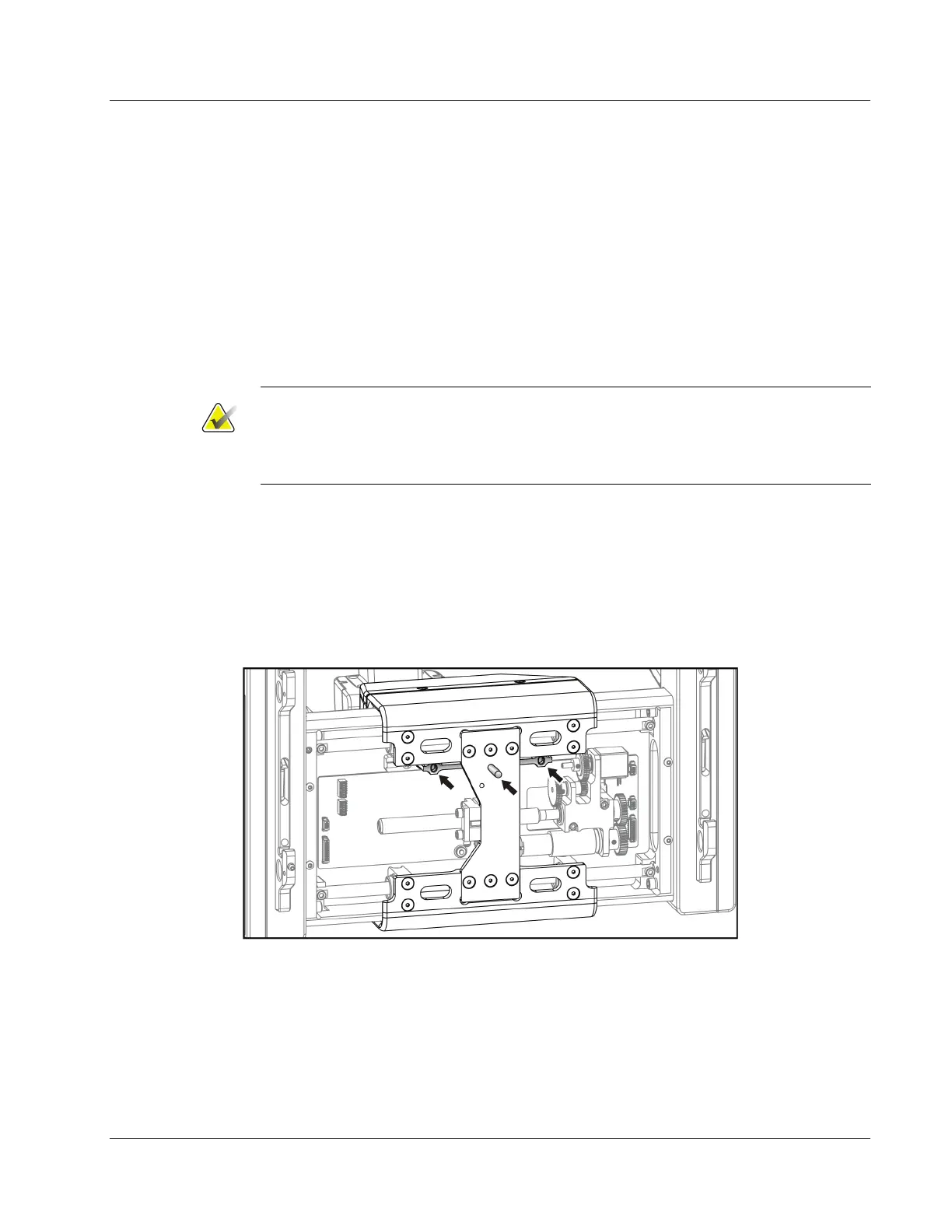
The following figure shows the pin in the center hole.
2. Apply power to the Biopsy Guidance Module.
3. Determine the X-axis encoder scale factor (counts/mm) using the dowel pin (MME-
01182) to locate the Xmin reference hole on the carriage (hole furthest to the right
side when looking from the back. Note the X-axis encoder count displayed value
corresponding to the current position. Reposition the dowel pin at the Xmax
reference hole on the carriage (hole furthest to the left side when looking from the
back), and again note the corresponding encoder count.
Figure 46: X-axis Reference Hole Locations and Y-axis Lead Screw Adjustment
Appendix C