Affirm Breast Biopsy Guidance System Service Manual
Appendix C: Hardware Range Calibration
Page 74 MAN-05754 Revision 002
4. Jog the Y-axis towards the rear of the Breast Platform until the Y-axis lead screw is
visible (see previous figure).
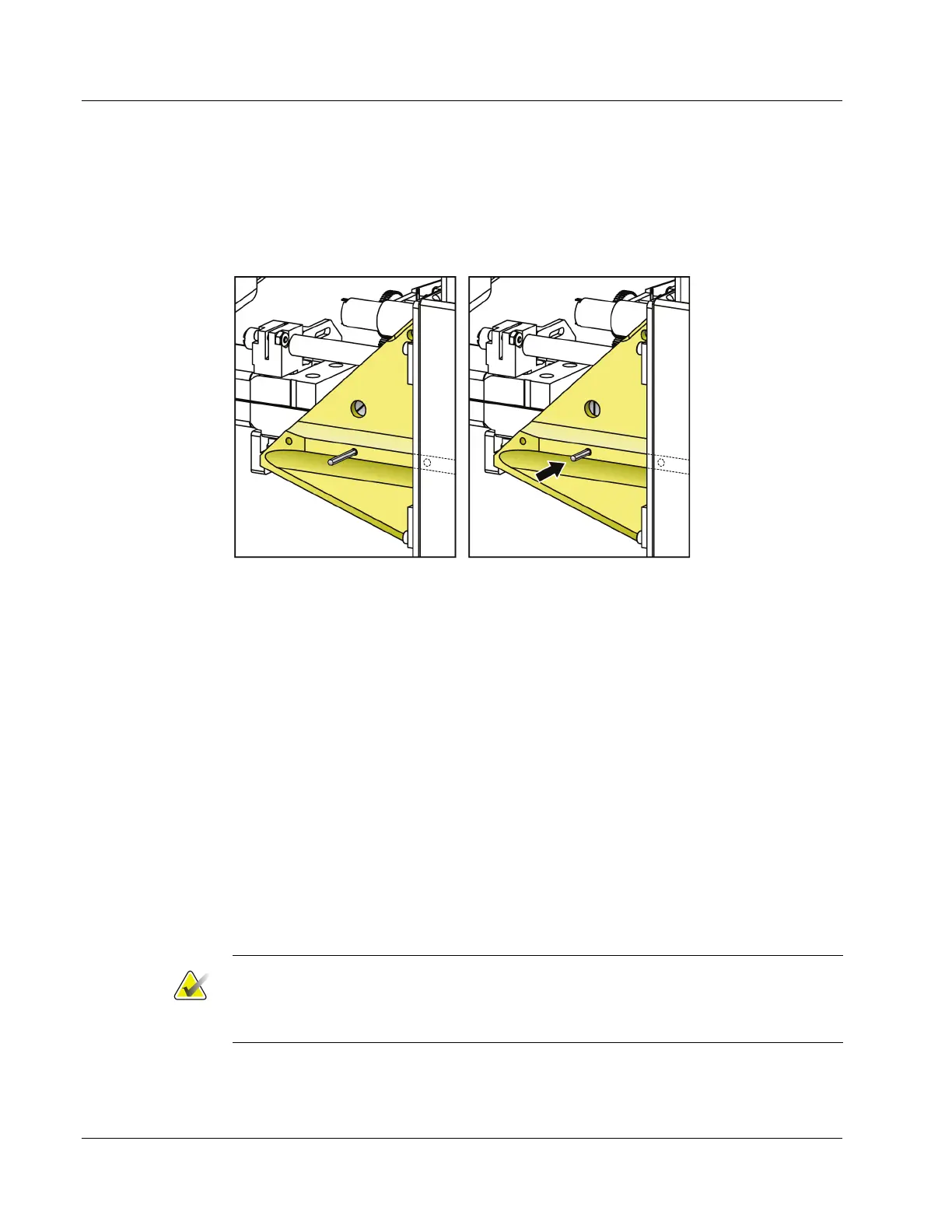
5. Place the dowel pin in the center hole in the top of the Y-axis Component Mount (see
following figure). Notice the slot visible in the large hole near the dowel pin is off
center. This slot aligns with the pocket that the dowel pin drops into.
Figure 47: Placing the Y-axis Dowel Pin
6. Turn the Y-axis lead screw (accessed with the bottom cover removed)
counterclockwise and stop as soon as the dowel pin drops (it only moves a few
millimeters). Light pressure may be used to move the dowel pin down. For reference,
the slot in the large hole should be centered (the slot is shown in the previous figure).
7. Using the Z-axis Calibration Tool (TLS-02432), note the -Zmin (closest to the breast
tray) encoder count, and the Zmax (farthest from the breast tray) encoder count.
8. The encoder scale factors for each axis are computed as follows:
• X-axis: SFX = (Enc_count@Xmax – Enc_count@Xmin)/70.0 counts/mm
• Y-axis: SFY = (Enc_count@Ymax – Enc_count@Ymin)/70.0 counts/mm
• Z-axis: SFZ = (Enc_count@Zmax – Enc_count@Zmin)/140.0 counts/mm
The computed scale factors should not differ from the default design values by more
than ±2%; the design values are:
• X-axis: 192.4 counts/mm
• Y-axis: 192.4 counts/mm
• Z-axis: 93.4 counts/mm
Note
A greater deviation from default design values is likely to be caused by incorrect
placement of the dowel pin or calibration tool during calibration. The X- and Y-axis
scale factors are negative because encoder counts decrease with increasing X or Y.