GX-Series Control Panel Installation and Setup Guide
6-70
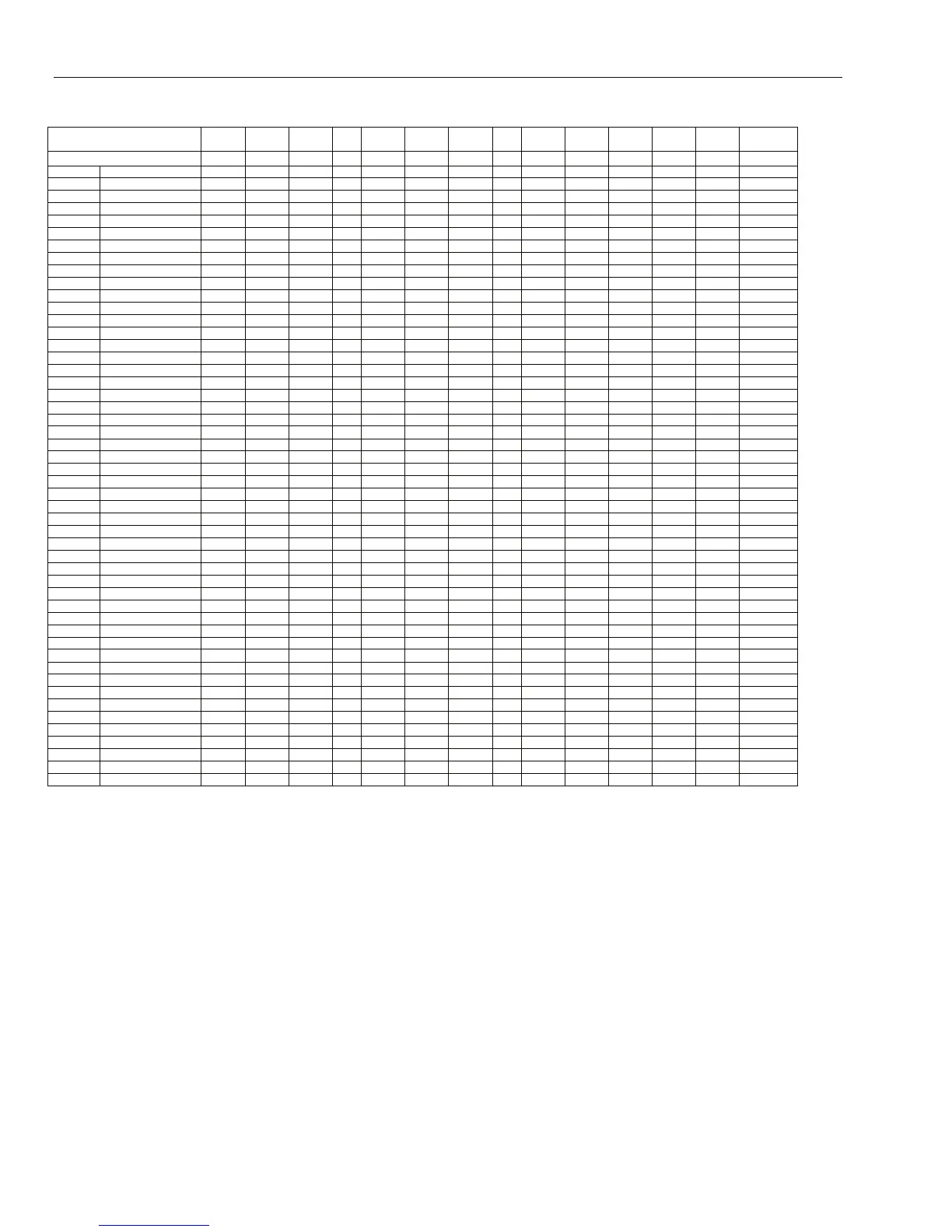
Output Functions Timer-A Timer-B
Walk
Test
Zone
Omit Warning
Custom
A
Custom
B Test
Reset
RQD Mask
Valid
cd
Fail
Set Duress
Illegal
Code
Zone Function 29 30 31 32 33 34 35 36 37 38 39 40 41 42
01 Final
- - U O A - - - S? - - - - -
-02 Exit
- - U O A - - - S? - - - - -
03 Intruder
- - U O A - - - S? - - - - -
04 24 Hours
- - U O A - - - S? - - - - -
05 Security
- - U O A - - - S? - - - - -
06 Dual
- - U O A - - - S? - - - - -
07 Entry
- - U O A - - - S? - - - - -
08 Push Set
- - U O A - - - - - - - - -
09 Keyswitch
- - U O A - - - - - - UX - -
10 Secure Final
- - U O A - - - - - - - - -
11 Part Final
- - U O A - - - - - - - - -
12 Part Entry
- - U O A - - - - - - - - -
13 PA
- - U O A - - - - - - - - -
14 PA Silent
- - U O A - - - - - - - - -
15 PA Delay
- - U O A - - - - - - - - -
16 PA Delay Silent
- - U O A - - - - - - - - -
17 Link
? ? U? O? ? ? ? ? ? ? ? ? ? ?
18 Spare
- - - - A - - - - - - - - -
19 Fire
- - U O A - - - A? - - - - -
20 Tamper
- - U O A - - - A? - - - - -
21 Bell Tamper
- - U O A - - - A? - - - - -
22 Beam Pair
- - U O A - - - - - - - - -
23 Battery Low
- - U O A - - - - - - - - -
24 Line Fail
- - U O A - - - - - - - - -
25 AC Fail
- - U O A - - - - - - - - -
26 Log
- - U O A - - - - - - - - -
27 Remote Access
- - U O A - - - - - - - - -
28 Video
- - U O A - - - S? - - - - -
29 Video Exit
- - U O A - - - S? - - - - -
30 Intruder Delay
- - U O A - - - S? - - - - -
31 Log Delay
- - U O A - - - - - - - - -
32 Set Log
- - U O A - - - - - - - - -
33 Custom-A
? ? ? O? ? ? ? ? ? ? ? ? ? ?
34 Custom-B
? ? ? O? ? ? ? ? ? ? ? ? ? ?
35 Exit Guard
L L LO L L L L L L L L L L L
36 Mask
- - - - - - - - - SPE - - - -
37 Urgent
- - U O A - - - A? - - - - -
38 PA Unset
- - U O A - - - U? - - - - -
39 Keyswitch Reset
- - U O A - - - - - - - - -
40 Bell Fail
- - - - A - - - - - - - - -
41 Intr Low
- - U O A - - - S? - - - - -
42 Intr High
- - U O A - - - S? - - - - -
43 PSU Fault
- - U O A - - - - - - - - -
44-46 Not Used
- - U O A - - - - - - - - -
47 Vibration
- - U O A - - - A? - - - - -
48 ATM-1
- - U O A - - - A? - - - - -
49 ATM-2
- - U O A - - - A? - - - - -
50 ATM-3
- - U O A - - - A? - - - - -
51 ATM-4
- - U O A - - - A? - - - - -
52 Alarm Extend
- - U O A - - - A? - - - - -
Key:
S = Activates when system is set (armed)
P = Activates when system is Part set (Part armed)
U = Unset (disarmed)
A = Activated in any condition
- = No effect
? = Activation dependant on system programming
X = Activates during Exit Time
E = Activates during Entry
L = Switches output off if linked to destination output
T = Activates if zone resistance is less than value for tamper s/c or greater than value for tamper o/c
O = Activates when zone is omitted (bypassed)
Table 6-21. Output Activations per Zone
 Loading...


