GX-Series Control Panel Installation and Setup Guide
6-48
46 = Resistance Select
RIOs, revision 1.2 and above, allow the zones to be programmed with different resistance preset values for
zone status activation. This feature allows selection of End Of Line or Double Balanced zone resistance
types. The on-board zones can also be modified using this feature.
The “EOL/Dbl. Bal.” resistance types are selectable from this option. The system default value is 1k Fault
(Double Balanced). There are 10 preset pre-programmable resistance configurations:
1 = Preset 1 (BAL); 2 = Preset 1(EOL); 3 = Preset 2 (BAL); 4 = Preset 2 (EOL); 5 = Preset 3 (BAL);
6 = Preset 3 (EOL); 7 = Preset 4 (BAL); 8 = Preset 4 (EOL); 9 = 1K Fault (BAL); 10 = 1K Fault (EOL).
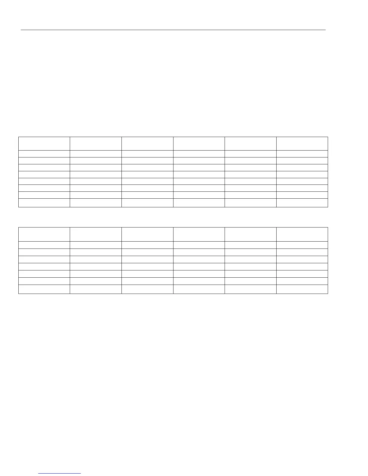
The tables that follow shows the resistance windows for each type:
NOTE: For UL 1076 installations, use 1K Ohm Single EOL configuration for all protective zones. Use EOL
resistor P/N 300-02343 supplied in SAP0166 package.
Option 01 - 1k Option 03 – 2.2k Option 05 – 4.7k Option 07 – 5.6k
Option 09 - 1k
Fault
Tamper S/C 0 – 800 0 – 1800 0 – 3700 0 -1400 0 - 800
Low Res 800 – 900 1800 – 2000 3700 – 4200 1400 – 2800 800 - 900
Normal 900 – 1200 2000 – 2500 4200 – 5500 2800 – 8400 900 -1200
High Res 1200 – 1300 2500 – 2700 5500 – 6500 8400 – 9800 1200 - 1300
Open 1300 – 12000 2700 – 12000 6500 – 19000 9800 – 12600 1300 - 3500
Fault - - - - 3500 - 4500
Masked 12000 – 19000 12000 – 15000 19000 – 22000 12600 – 22000 4500 - 19000
Tamper O/C 19000 – infinity 15000 – infinity 22000 – infinity 22000 – infinity 19000 – infinity
Table 6-9. Preset value limits (ohms) - double balanced
Option 02 - 1k Option 04 – 2.2k Option 06 – 4.7k Option 08 – 5.6k
Option 10 -1k
Fault
Tamper S/C 0 – 800 0 – 1800 0 – 3700 0 – 1400 0 - 800
Low Res 800 – 900 1800 – 2000 3700 – 4200 1400 – 2800 800 - 900
Normal 900 – 1200 2000 – 2500 4200 – 5500 2800 – 8400 900 - 1200
High Res 1200 – 1300 2500 – 2700 5500 – 6500 8400 – 9800 1200 - 1300
Fault - - - - 1300 - 4500
Masked 1300 – 12000 2700 – 12000 6500 – 19000 9800 – 19000 4500 - 19000
Open 12000 – infinity 12000 – infinity 19000 – infinity 19000 – infinity 19000 – infinity
Table 6-10. Preset value limits (ohms) - end of line
When a preset is selected, this will be the zone resistance range used by every zone on the system. Each zone
on the system can be further customized to a specific preset by using menu option 52.9, Resistance Select.
47 = Set Confirm
This parameter allows the system to emit a short double beep when the system/group has set (armed). There
are three options:
0 = Off
No indication.
1 = Alert on Set
A double beep when the system has set (armed).
2 = Alert on Comm {Required for UL installations}
A double beep after a successful signal to the ARC that setting (arming) has occurred.
48 = Alarm Limits
This parameter allows the user to program the maximum number of alarms, per group, which may be
transmitted to an Alarm Receiving Center in any set (armed) period. There are three options:
1 = No of Alarms
 Loading...


