Input Calibration
90 UDC2300 Controller Product Manual 12/00
Procedure
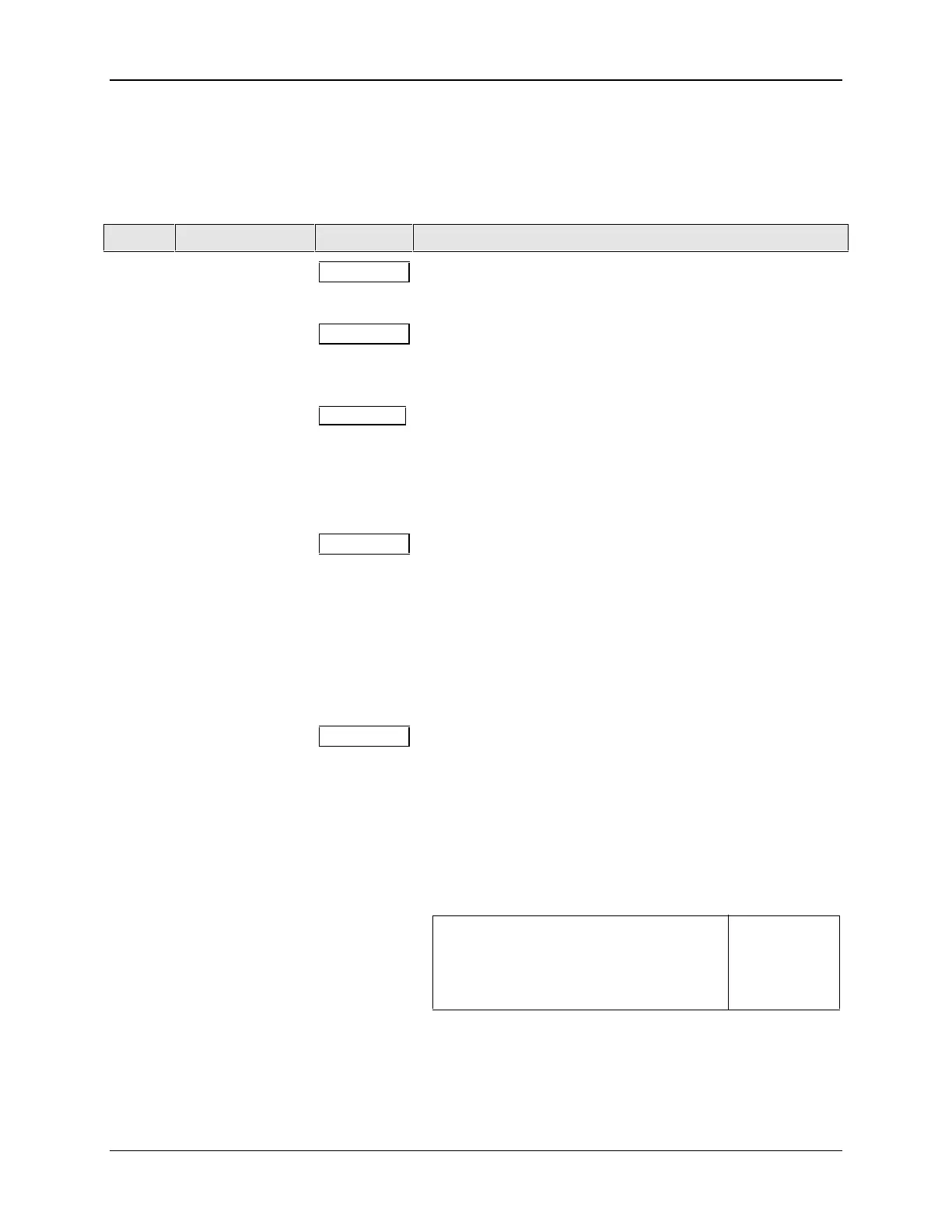
The calibration procedure for Input #1 is listed in Table 8-8. The numeric codes are also
listed.
Table 8-8 Input 1 Calibration Procedure (Numeric Code 10000)
Step Operation Press Result
1
Enter Calibration
Mode
SET UP
until you see
Upper Display = CAL ( - - - - )
Lower Display = INPUT1 (10000)
FUNCTION
You will see:
Upper Display = DIS ( 0 )
Lower Display = CALIN1 (10001)
▲
The calibration sequence is enabled and you will see:
Upper Display = BEGN ( 1 )
Lower Display = CALIN1 (10001)
At the completion of the sequence, the selection
automatically reverts to disable.
2
Calibrate 0 %
FUNCTION
You will see:
Upper Display = APLY ( 2 )
Lower Display = IN1ZRO (10002)
• Adjust your calibration device to an output signal equal to
the 0 % range value for your particular input sensor. See
Table 8-1 for Voltage, Degrees, or Resistance
equivalents for 0 % range values.
• Wait 15 seconds, then go to the next step.
3
Calibrate 100 %
FUNCTION
You will see:
Upper Display = APLY ( 2 )
Lower Display = IN1SPN (10003)
• Adjust your calibration device to an output signal equal to
the 100 % range value for your particular input sensor.
See Table 8-1 for Voltage, Degrees, or Resistance
equivalents for 100 % range values.
• Wait 15 seconds, and
If … Then …
you are calibrating a Thermocouple input go to step 4
you are calibrating other than a go to step 5
Thermocouple input
Continued next page

 Loading...


