Input Calibration
12/00 UDC2300 Controller Product Manual 93
Procedure
The calibration procedure for Input #2 is listed in Table 8-9. The numeric codes are also
listed.
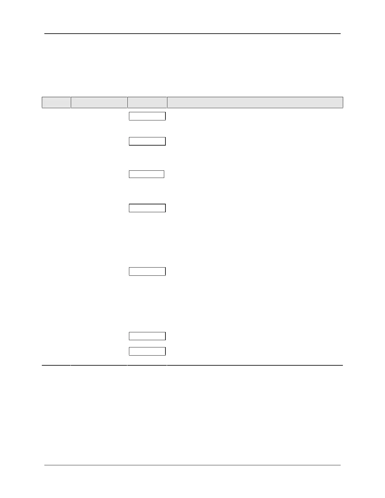
Table 8-9 Input 2 Calibration Procedure (Numeric Code 20000)
Step Operation Press Result
1
Enter Calibration
Mode
SET UP
until you see
Upper Display = CAL ( - - - - )
Lower Display = INPUT2 (20000)
FUNCTION
You will see:
Upper Display = DIS ( 0 )
Lower Display = CALIN2 (20001)
▲
You will see:
Upper Display = BEGN ( 1 )
Lower Display = CALIN2 (20001)
2
Calibrate 0 %
FUNCTION
You will see:
Upper Display = APLY ( 2 )
Lower Display = IN2ZRO (20002)
• Adjust your calibration device to an output signal equal to
the 0 % range value for your particular input sensor.
• Wait 15 seconds, then go to the next step.
3
Calibrate 100 %
FUNCTION
You will see:
Upper Display = APLY ( 2 )
Lower Display = IN2SPN (20003)
• Adjust your calibration device to an output signal equal to
the 100 % range value for your particular input sensor.
• Wait 15 seconds, then go to the next step.
4
FUNCTION
The controller stores the calibration constants.Exit the
Calibration Mode
DISPLAY
To store the calibration constants and exit the calibration
mode.
8.8 Restore Factory Calibration
Introduction
The factory calibration constants for all the input actuation types that can be used with the
controller are stored in its nonvolatile memory. Thus, you can quickly restore the
“Factory Calibration” for a given input actuation type by simply changing the actuation
type to another type and then changing it back to the original type.
Refer to Table 8-10 Restore Factory Calibration for procedure.

 Loading...


