Input Calibration
12/00 UDC2300 Controller Product Manual 91
Step Operation Press Result
4
Check the Cold
Junction
Temperature
FUNCTION
The calculations for zero and span are now stored and you
will see:
Upper Display = The cold junction temperature at the rear
terminals
Lower Display = CJTEMP (10004)
The value in the upper display is in tenths of a degree. It is
the current reading of the temperature as measured at the
thermocouple terminals and recognized by the controller.
You can change this value, if it is in error, using the
[▲] [▼] keys.
NOTE: The accuracy of the controller is directly affected by
the accuracy of this value. Change this value only if the zero
and span calibration procedures did not bring the controller
within the specified accuracy requirements.
5
Exit the
Calibration Mode
FUNCTION
then
The controller stores the calibration constants and exits the
calibration mode.
DISPLAY
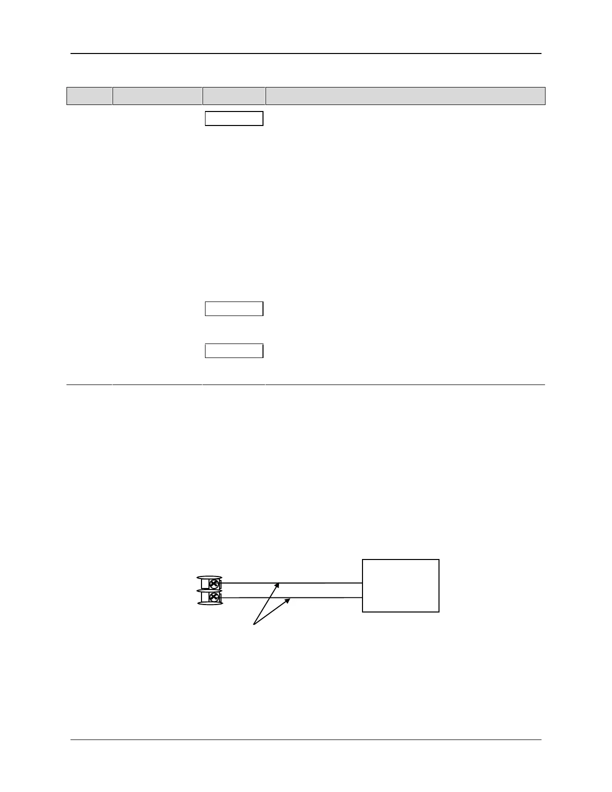
8.6 Input 2 Set Up Wiring
0 to 20 mA or 4 to 20 mA Inputs
• Use the copper leads and connect the calibrator to the rear terminals of Input #2
(see Figure 8-7).
• Make sure jumper at S201 is set for mA (position 1).
See Figure 2-2 Jumper Placements.
24878
15
16
+
_
4 to 20
mA
Source
+
_
Copper
Leads
0 – 20 mA
or
Figure 8-7 Wiring Connections for 4 to 20 mA Input – Input 2

 Loading...


