Installation
14 UDC2300 Controller Product Manual 12/00
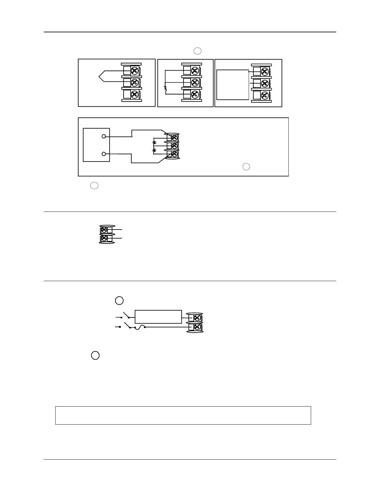
8
7
6
R
+
-
mV, Volts (except 0-10V),
Milliamperes, or Radiamatic
Thermocouple
Platinum
RTD
24857
8
7
6
R
+
-
mV, Volt,
or
Milliampere
Source
8
7
6
R
+
-
0 to 10 Volts
The voltage divider for 0 to 10
Volts is supplied with the
controller when the input is
specified. You must install it
when you wire the controller
before start-up. 1
Volt
Source
8
7
6
+
_
R
_
+
1
2
3
1 These inputs are wired differently than the UDC2000
RTD
1
Use
Thermocouple
extension wire
only
Figure 2-7 Input 1 Connections
15
16
+
0 to 20 mA,
4 to 20 mA,
0 to 5 Volts
1 to 5 Volts
_
24858
See “Preliminary Checks” in this
section of the Product Manual for
jumper selections.
Figure 2-8 Input 2 Connections
1
Control relays 1 and 2 are configured N.O. as shipped. Alarm relays
1 and 2 are configured N.C. as shipped. N.O. or N.C. configurations
are selectable by jumpers on the Main printed wiring boards.
See “Preliminary Checks” in this section of the
Product Manual for details.
Each SPST relay is rated at 5A, 120
Vac and 30 Vdc, 2.5 A 240 Vac. User-provided fuses should be sized
accordingly. For solid state relay outputs, see Figure 2-13.
24859
1
5
4
Load
Supply
Power
5 amp Fast Blo
Control Relay #1
Load
OUT1 OUT2/ALM2
9
10
See Figure 2-15 for Alarm and Duplex Output Connections.
See Table 2-3 and Table 2-4 for Control and Alarm Relay Contact information.
Figure 2-9 Electromechanical Relay Output

 Loading...


