Input Calibration
12/00 UDC2300 Controller Product Manual 89
24876
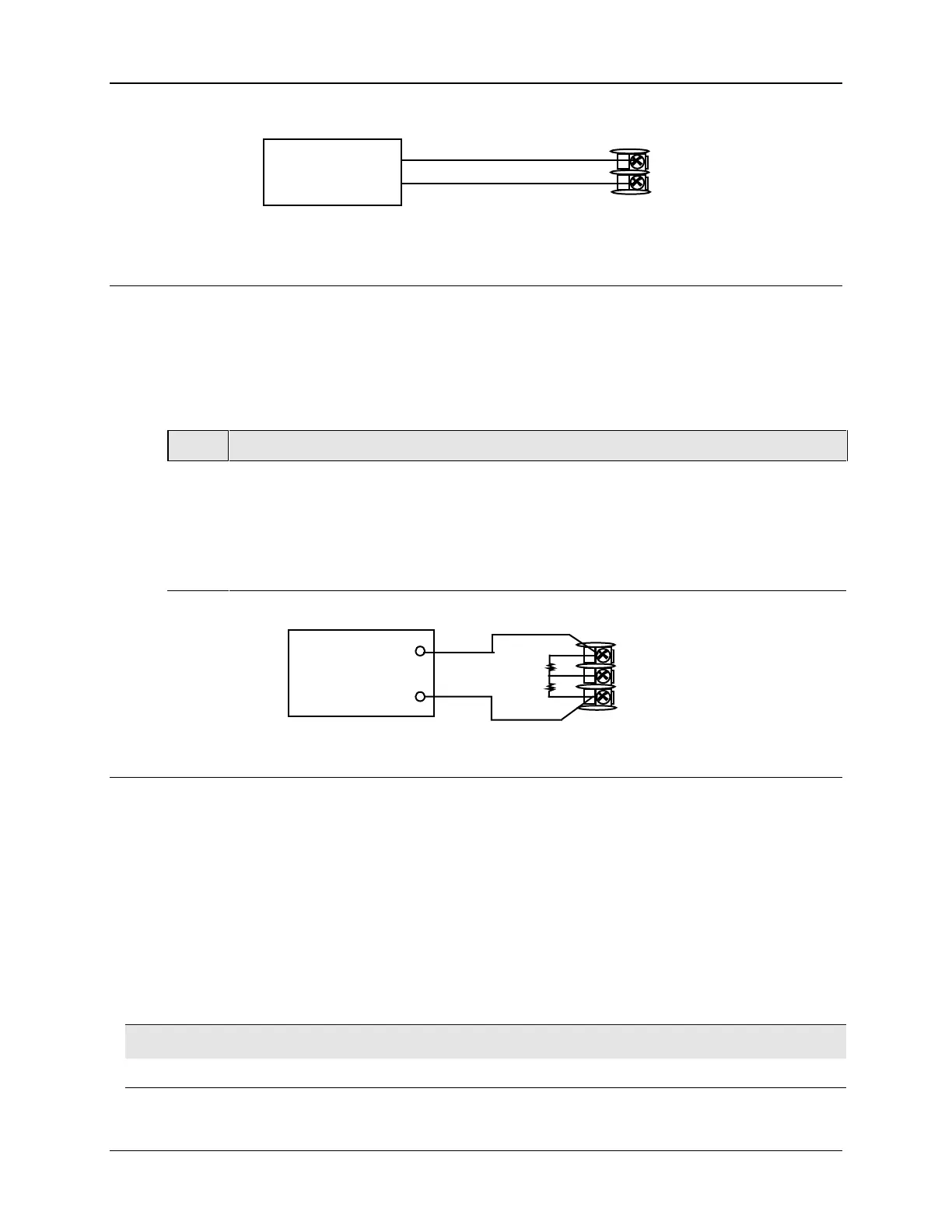
Milliampere,
Millivolt, Volt
Source
8
7
+
_
+
_
Figure 8-5 Wiring Connections for Radiamatic, Milliampere, Millivolts, or
Volts (Except 0 to 10 Volts)
0 to 10 Volts
Refer to Figure 8-6 and wire the controller according to the procedure given in Table 8-7.
Make sure the jumper at S101 is in parked position. See Figure 2-2 Jumper Placements.
Table 8-7 Set Up Wiring Procedure for 0 to 10 Volts
Step Action
1
Connect the copper leads from the calibrator to the Input #1 terminals as shown in
Figure 8-6.
2
Place current source at zero before switching on.
3
Do not switch current sources ON/OFF while connected to the UDC2300 input.
24877
Volt
Source
8
7
6
+
_
R
_
+
1
2
3
Figure 8-6 Wiring Connections for 0 to 10 Volts
8.5 Input 1 Calibration Procedure
Preliminary Steps
• Apply power and allow the controller to warm up for 30 minutes before you calibrate.
• Please read Subsection 8.4 – Input 1 Set Up Wiring before beginning the procedure.
• Make sure you have LOCK set to NONE. See Subsection 4.5 - Tuning Set Up
Group.
• See Table 8-1 for Voltage vs. Resistance equivalents or 0 % and 100 % range values.
CAUTION
For linear inputs, avoid step changes in inputs. Vary smoothly from initial value to final 100 % value.

 Loading...


