Installation
12 UDC2300 Controller Product Manual 12/00
Permissible Wiring Bundling
Table 2-6 Permissible Wiring Bundling
Bundle No. Wire Functions
1
• Line power wiring
• Earth ground wiring
• Control relay output wiring
• Line voltage alarm wiring
2Analog signal wire, such as:
• Input signal wire (thermocouple, 4 to 20 mA, etc.)
• 4-20 mA output signal wiring
Digital input signals
3
• Low voltage alarm relay output wiring
• Low voltage wiring to solid state type control circuits
2.7 Wiring Diagrams
Identify Your Wiring Requirements
To determine the appropriate diagrams for wiring your controller, refer to the model
number interpretation in this section. The model number of the controller can be found on
the outside of the case.
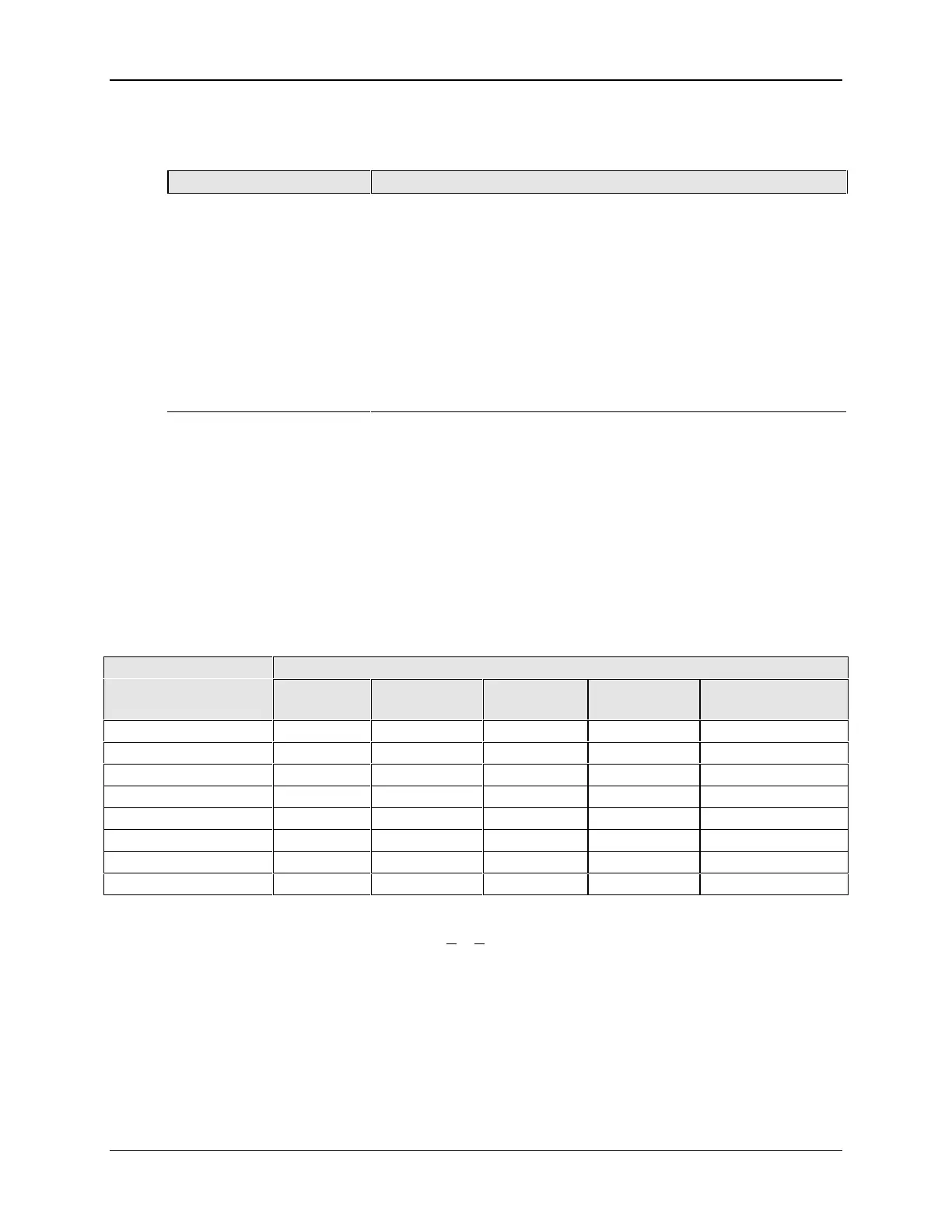
Universal Output Functionality and Restrictions
Table 2-7 Universal Output Functionality and Restrictions
Output/Socket
Output Type Current
Output
Relay #1 Relay #2 Relay #3 Auxiliary Output
Time Simplex 1 N/I Output 1 Alarm 2 Alarm 1 Not Needed
Time Simplex 2 N/A N/I Output Alarm 1 Not Needed
Current Simplex Output N/I Alarm 2 Alarm 1 Not Needed
Time Duplex or TPSC N/I Output 1 Output 2 Alarm 1 Not Needed
Current Dup. 100 % Output 1 N/I Alarm 2 Alarm 1 Not Needed
Current Dup. 50 % Output 1 N/I Alarm 2 Alarm 1 Output 2
Current/Time Output 1 N/I Output 2 Alarm 1 Not Needed
Time/Current Output 2 N/I Output 1 Alarm 1 Not Needed
N/I = Not Installed
N/A = The output form or the individual output is Not A
vailable or is not used for this output form.
Not Needed =Auxiliary Output is not needed to provide the desired output function and can be used for
another purpose. Auxiliary Output could also be used as a substitute for current Output 1.

 Loading...


