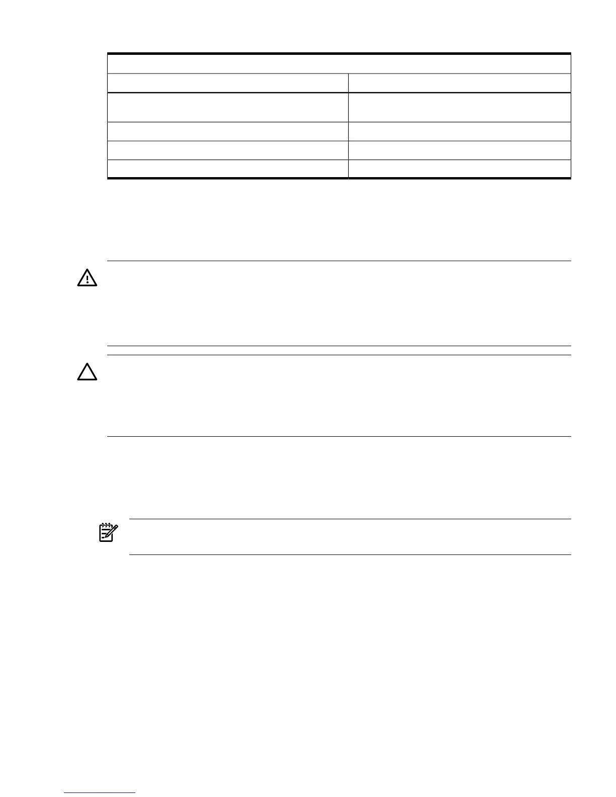
Table 4-4 DIMM Filler Requirements for 32 DIMM Extender Board (continued)
32 DIMM Extender Board
Fillers required
1
DIMMs Loaded
4 fillers total: 2 fillers in quads 5, 7 quad 6 remains
unfilled
20 DIMMs in quads 0, 1, 2, 3, and 4
No fillers required24 DIMMs in quads 0, 1, 2, 3, 4, and 5
No fillers required28 DIMMs in quads 0, 1, 2, 3, 4, 5, and 6
No fillers required32 DIMMs in quads 0, 1, 2, 3, 4, 5, 6, and 7
1 One DIMM filler board covers two DIMM adjacent slots.
Removing and Replacing the Processor Extender Board
The processor extender board is located directly under the memory extender board. The processor
extender board can hold between one and four processors.
WARNING! Ensure that the server is powered off and all power sources have been disconnected
from the server prior to removing or replacing the processor extender board.
Voltages are present at various locations within the server whenever an AC power source is
connected. This voltage is present even when the main power switch is in the off position.
Failure to observe this warning can result in personal injury or damage to equipment.
CAUTION: Failure to properly complete the steps in this procedure will result in erratic server
behavior or server failure. For assistance with this procedure contact your local HP Authorized
Service Provider.
Observe all ESD safety precautions before attempting this procedure. Failure to follow ESD safety
precautions can result in damage to the server.
Removing the Processor Extender Board
To remove the processor extender board, follow these steps:
1. If rack mounted, slide the HP server out from the rack until it stops. See “Extending the
Server From the Rack” (page 31).
NOTE: The processor extender board can be removed without removing the server from
the rack.
2. Remove the front bezel. See “Removing the Front Bezel” (page 34).
3. Remove the front cover. See “Removing the Front Cover” (page 35).
4. Press the latch on the extraction levers located on each side of the processor extender board.
Figure 4-11 shows how to open the processor extender board latches.
Removing and Replacing the Processor Extender Board 43
 Loading...


