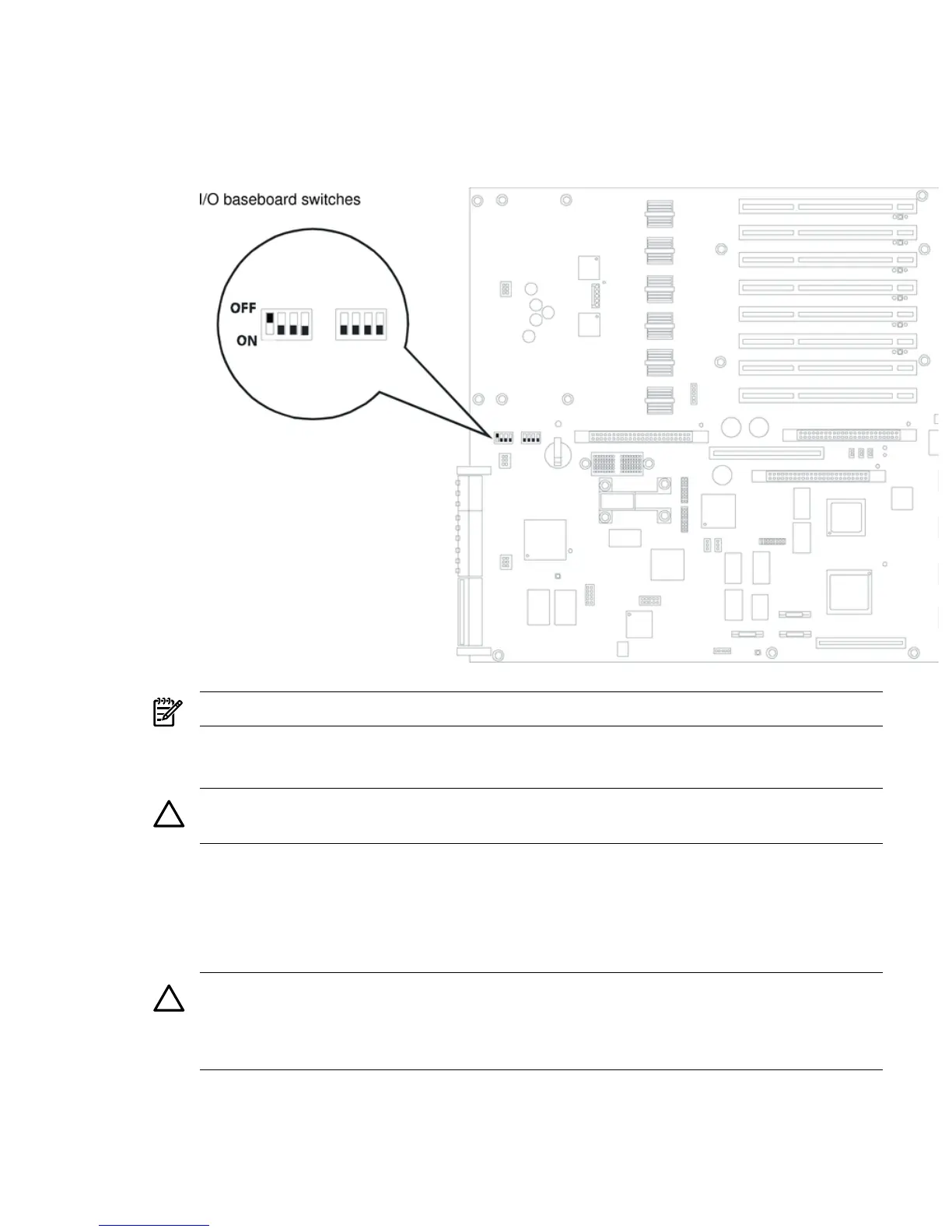
1. Depending on the type of processor you have installed, set the I/O baseboard dip switch
SW1503 (position 4) (Figure 4-24) as follows.
• Itanium 2 processor - Off
• MX2 dual-core processor - On
Figure 4-24 I/O Baseboard Switches
NOTE: The I/O baseboard is large. Use care when sliding it into the server chassis.
2. Align the I/O baseboard assembly rails with the chassis slots and slide the assembly into the
chassis until it stops against the midplane riser board socket.
CAUTION: Ensure the I/O baseboard locking lever is in the “up” position or the I/O
baseboard hangs up before engaging the midplane riser board socket.
3. With the I/O baseboard flush against the midplane riser board socket, push down firmly on
the locking lever until the I/O baseboard plugs all the way into the midplane riser board
socket.
4. Replace the three chassis fan units. “Replacing a Hot-Swappable Chassis Fan Unit” (page 55).
5. Plug in all external cabling in to the rear ports of the I/O baseboard.
CAUTION: When plugging the SCSI cables, note the labeling on the SCSI A and SCSI B
channel cables. You must match each cable with its appropriate socket on the SCSI HBA. If
the cables are mismatched your server might not reboot. Both cables and sockets are clearly
marked with the correct channel.
6. Plug in the internal SCSI cable(s) to the HBA board in PCI slot 1.
7. Replace the top cover. See “Replacing the Top Cover” (page 36)
8. If rack mounted, slide the server into the rack until it stops. See “Inserting the Server into
the Rack” (page 32).
Removing and Replacing the I/O Baseboard 59
 Loading...


