6·14
Removal
and
Replacement
Portable
PLUS
Computer
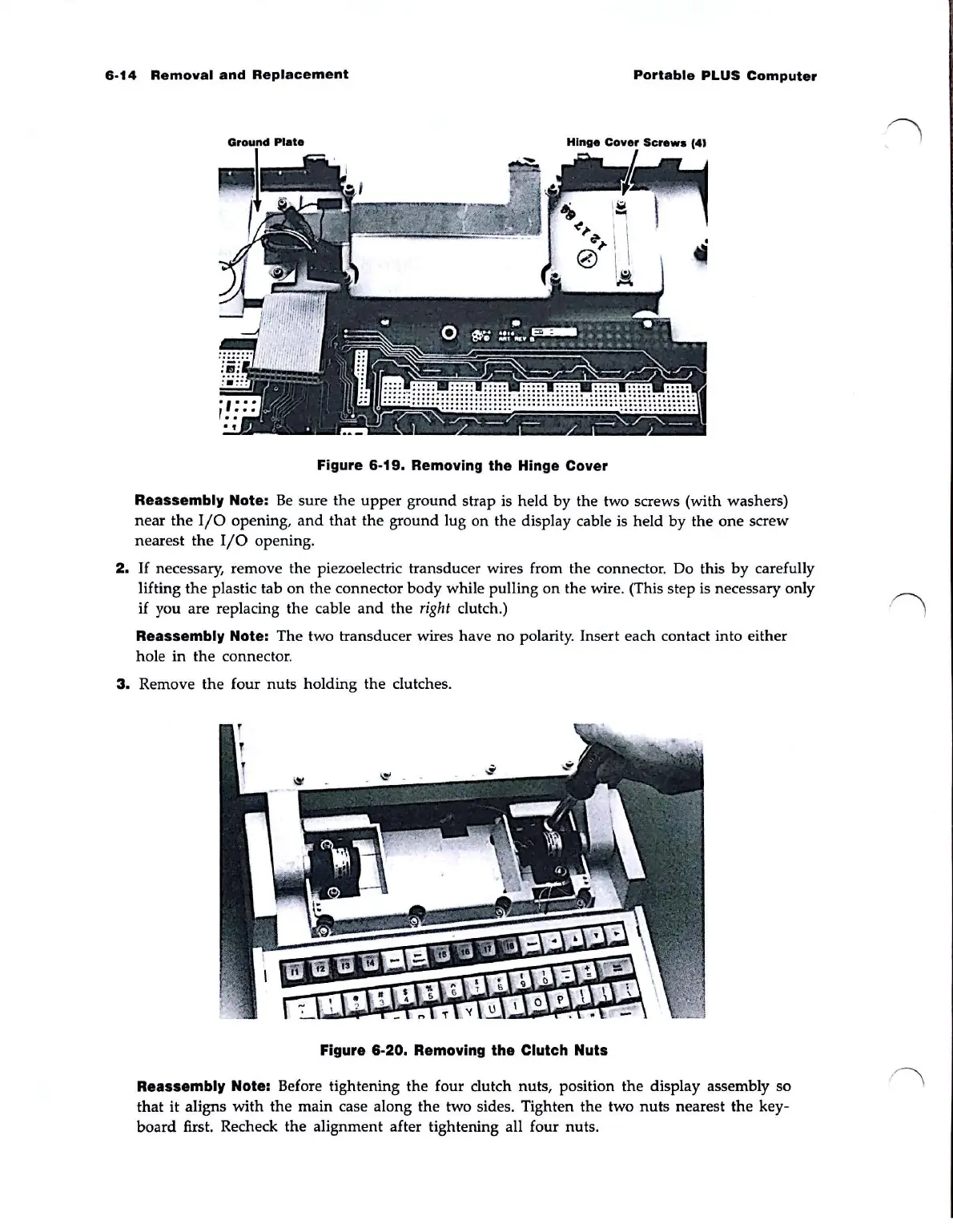
Figure
6·19.
Removing
the
Hinge Cover
Reassembly Note:
Be
sure
the
upper
ground
strap is held
by
the
two screws (with washers)
near
the
I/O
opening,
and
that
the
ground
lug on
the
display cable is held
by
the
one
screw
nearest
the
I/O
opening.
2.
If
necessary, remove the piezoelectric transducer wires from the connector. Do this
by
carefully
lifting
the
plastic tab
on
the
connector
body
while pulling
on
the wire. (This step is necessary only
if you are replacing
the
cable
and
the
right
clutch.)
Reassembly Note:
The
two transducer wires have
no
polarity. Insert each contact into either
hole
in
the
connector.
3.
Remove
the
four
nuts
holding
the
clutches.
Figure
6·20.
Removing the Clutch Nuts
Reassembly Note: Before tightening
the
four
dutch
nuts, position
the
display assembly so
that
it
aligns
with
the
main case along
the
two sides. Tighten
the
two
nuts
nearest
the
key-
board
first. Recheck
the
alignment after tightening all four nuts.