8-24
Troubleshooting
Portable
PLUS Computer
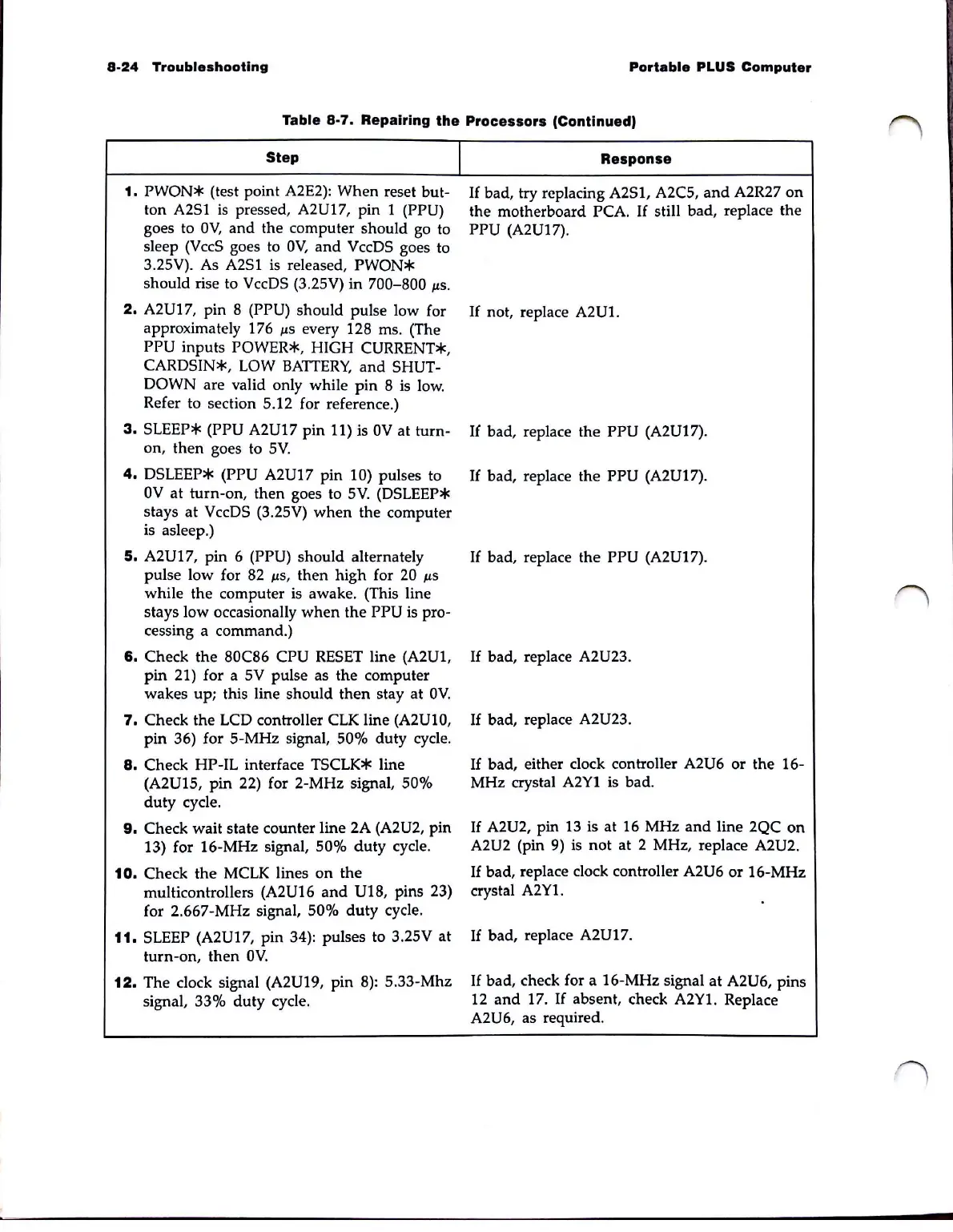
Table 8-7_ Repairing
the
Processors (Continued,
Step
1.
PWON*
(test point A2E2):
When
reset but-
ton A2S1
is
pressed, A2U17, pin 1 (PPU)
goes to
OV,
and
the computer should go to
sleep (VccS goes to
OV,
and
VccDS goes to
3.2SV). As A2S1 is released,
PWON*
should rise to VccDS
(3
.2SV)
in
700-800
~s
.
2.
A2U17, pin 8 (PPU) should pulse low for
approximately 176
~s
every 128
ms
. (The
PPU inputs POWER*, HIGH CURRENT*,
CARDSIN*,
lOW
BATTERY,
and
SHUT-
DOWN
are valid only while
pin
8 is low.
Refer to section 5.12 for reference.)
3.
SlEEP*
(PPU A2U17 pin 11) is
OV
at turn-
on,
then
goes to
SV.
4.
DSlEEP*
(PPU A2U17
pin
10) pulses to
OV
at turn-on,
then
goes to
SV.
(DSlEEP*
stays
at
VccDS (3.2SV)
when
the computer
is asleep.)
5.
A2U17, pin 6 (PPU) should alternately
pulse low for 82
~s,
then
high for
20
~s
while
the
computer
is
awake. (This line
stays low occasionally
when
the
PPU is pro-
cessing a command.)
6.
Check
the
80C86 CPU
RESET
line (A2U1,
pin
21) for a SV pulse as
the
computer
wakes
up; this line
should
then
stay at
OV.
7.
Check
the
LCD controller
elK
line (A2UlO,
pin
36) for S-MHz signal, 50%
duty
cycle.
8.
Check
HP-Il
interface
TSClK*
line
(A2U1S,
pin
22) for 2-MHz signal, 50%
duty
cycle.
9.
Check wait state counter line 2A (A2U2, pin
13) for 16-MHz signal,
50%
duty
cycle.
10.
Check
the
MClK
lines
on
the
muIticontroIIers (A2U16
and
V18, pins 23)
for 2.667-
MHz
signal, 50%
duty
cycle.
11.
SLEEP (A2U17,
pin
34): pulses to 3.2SV at
turn-on,
then
OV.
12.
The clock signal (A2U19, pin
8):
S.33-Mhz
signal, 33%
duty
cycle.
I
Response
If
bad, try replacing A2S1, A2CS,
and
A2R27
on
the motherboard PCA.
If
still bad, replace the
PPU (A2U17).
If
not, replace
A2Ul.
If
bad, replace
the
PPU (A2U17).
If
bad, replace
the
PPU (A2U17).
If
bad, replace
the
PPU (A2U17).
If
bad, replace A2U23.
If
bad, replace A2U23.
If
bad, either clock controller A2U6 or
the
16-
MHz crystal
A2Y1
is bad.
If
A2U2, pin
13
is at 16 MHz
and
line 2QC
on
A2U2 (pin 9)
is
not
at 2 MHz, replace A2U2.
If
bad, replace clock controller A2U6 or 16-MHz
crystal A2Yl.
If
bad, replace A2U17.
If
bad, check for a 16-MHz signal
at
A2U6, pins
12
and
17.
If
absent, check A2Yl. Replace
A2U6, as required.