Portable
PLUS
Computer
Troubleshooting
8-25
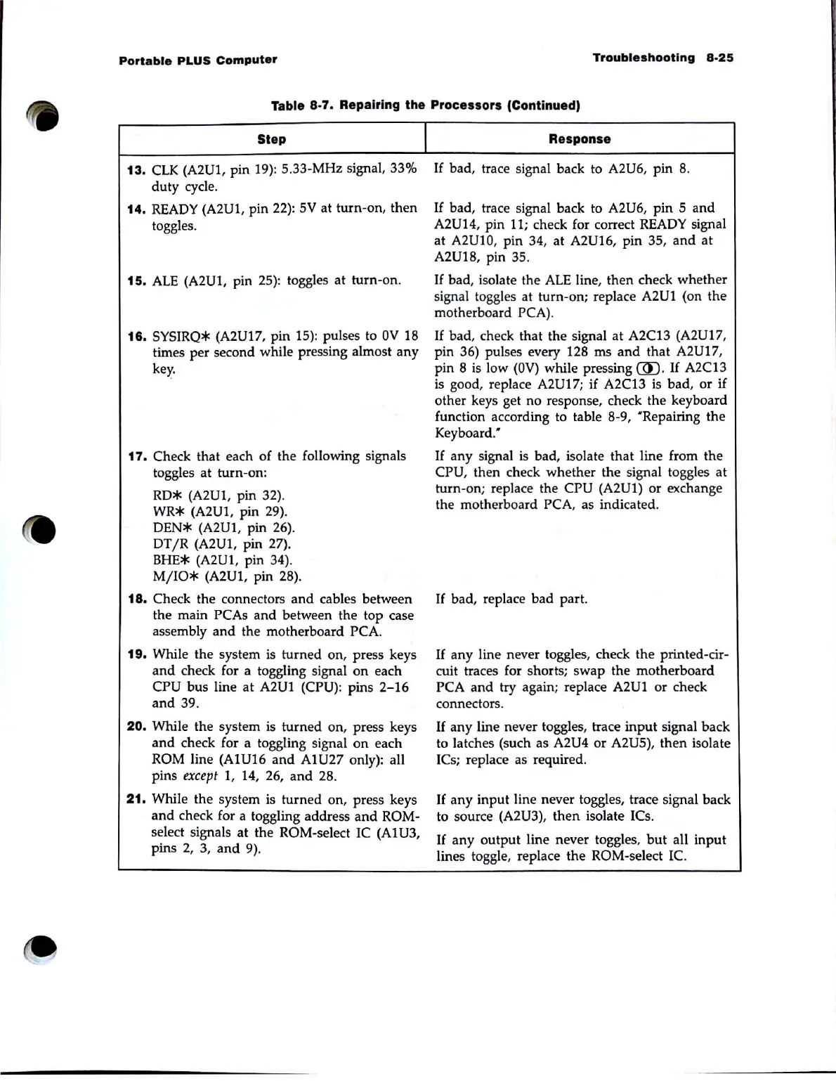
Table 8-7. Repairing the Processors (Continued)
Step
13.
ClK
(A2Ul, pin
19):
S.33-MHz signal, 33%
duty cycle.
14.
READY
(A2U1, pin
22):
SV
at turn-on, then
toggles.
15.
ALE
(A2U1, pin
2S)
: toggles at turn-on.
16.
SYSIRQ* (A2Ul7, pin IS): pulses to
OV
18
times per second while pressing almost
any
key.
17.
Check that each of the following signals
toggles at turn-on:
RD* (A2Ul, pin 32).
WR* (A2U1, pin 29).
DEN*
(A2Ul, pin
26).
DTjR
(A2U1, pin 27).
BHE*
(A2U1, pin 34).
MjIO*
(A2Ul, pin 28).
18. Check the connectors
and
cables between
the main PCAs
and
between the top case
assembly
and
the motherboard PCA.
19.
While the system
is
turned on, press keys
and
check for a toggling signal
on
each
CPU bus line
at
A2U1 (CPU): pins
2-16
and
39.
20.
While the system
is
turned on, press keys
and
check for a toggling signal
on
each
ROM line (A1Ul6
and
A1U27 only): all
pins
except
1, 14, 26,
and
28.
21.
While the system
is
turned on, press keys
and
check for a toggling address
and
ROM-
select signals at the ROM-select
IC
(A1U3,
pins
2,
3,
and
9).
I
Response
If
bad, trace signal back to A2U6, pin 8.
If
bad, trace signal back to A2U6, pin
Sand
A2U14, pin 11; check for correct
READY
signal
at A2UlO, pin 34, at A2Ul6, pin
3S,
and
at
A2Ul8, pin
3S
.
If
bad, isolate the
ALE
line, then check whether
signal toggles at turn-on; replace
A2U1 (on the
motherboard PCA).
If
bad, check that the signal at A2C13 (A2Ul7,
pin 36) pulses every 128 ms
and
that A2U17,
pin 8
is
low
(OV)
while pressing
(ID.
If
A2C13
is
good, replace A2U17; if A2C13
is
bad,
or
if
other keys get no response, check the keyboard
function according to table 8-9,
"Repairing the
Keyboard:
If
any signal
is
bad, isolate that line from the
CPU, then check whether the signal toggles at
turn-on; replace the
CPU (A2U1) or exchange
the motherboard
PCA, as indicated.
If
bad, replace bad part.
If
any line never toggles, check the printed-cir-
cuit traces for shorts; swap the motherboard
PCA
and
try
again; replace A2U1 or check
connectors.
If
any line never toggles, trace
input
signal back
to latches (such as
A2U4 or A2US), then isolate
ICs; replace as required.
If
any input line never toggles, trace signal back
to source
(A2U3), then isolate ICs.
If
any
output line never toggles,
but
all input
lines toggle, replace the ROM-select
Ie.