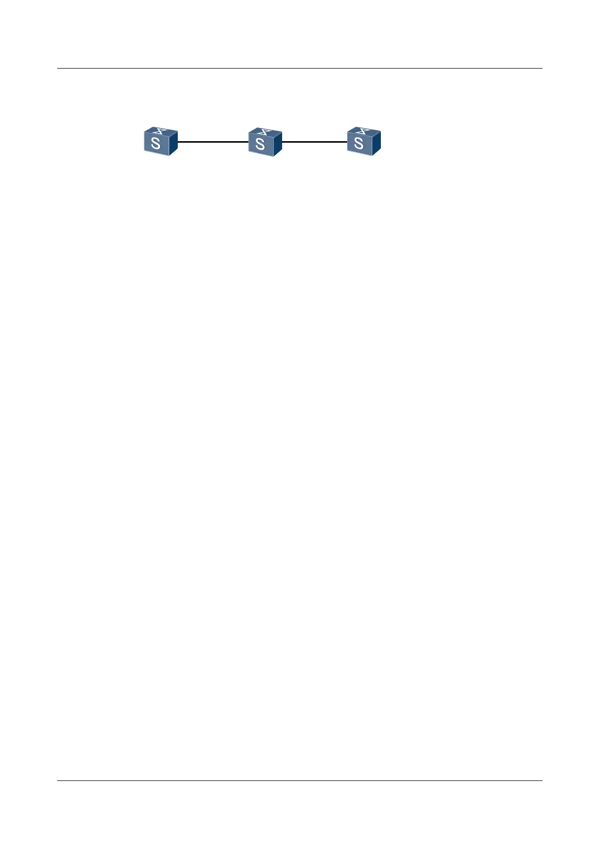
Figure 6-7 Networking diagram of IS-IS GR configuration
SwitchA
L1 L2
SwitchC
L1/L2
XGE0/0/1 XGE0/0/2
XGE0/0/1
XGE0/0/1
SwitchB
Switch Interface VLANIF interface IP address
SwitchA XGigabitEthernet0/0/1 VLANIF 10 100.1.1.1/24
SwitchB XGigabitEthernet0/0/1 VLANIF 20 100.2.1.2/24
SwitchC XGigabitEthernet0/0/1 VLANIF 10 100.1.1.2/24
SwitchC XGigabitEthernet0/0/2 VLANIF 20 100.2.1.1/24
Configuration Roadmap
The configuration roadmap is as follows:
1. Enable IS-IS on each Switch so that the Switches can be interconnected.
2. Configure GR in the IS-IS view on each Switch and configure the same interval for the
restart.
Data Preparation
To complete the configuration, you need the following data:
l ID of the VLAN that each interface belongs to, as shown in Figure 6-7
l IP address of each VLANIF interface, as shown in Figure 6-7
l System ID, level, and area ID of each Switch :
– Switch A: The system ID is 0000.0000.0001; the area ID is 10; the level is Level-1.
– Switch B: The system ID is 0000.0000.0002; the area ID is 10; the level is Level-2.
– Switch C: The system ID is 0000.0000.0003; the area ID is 10; the level is Level-1-2.
l Restart interval
Procedure
Step 1 Configure VLANs that the related interfaces belong to.
<Quidway> system-view
[Quidway] sysname SwitchA
[SwitchA] vlan 10
[SwitchA-Vlan10] quit
[SwitchA] interface xgigabitethernet 0/0/1
[SwitchA-XGigabitEthernet0/0/1] port hybrid pvid vlan 10
[SwitchA-XGigabitEthernet0/0/1] port hybrid untagged vlan 10
[SwitchA-XGigabitEthernet0/0/1] quit
The configurations of Switch B and Switch are similar to the configuration of Switch A, and
are not mentioned here.
Step 2 Assign an IP address to each VLANIF interface.
S6700 Series Ethernet Switches
Configuration Guide - IP Routing 6 IS-IS Configuration
Issue 01 (2012-03-15) Huawei Proprietary and Confidential
Copyright © Huawei Technologies Co., Ltd.
339
 Loading...