Fieldbus Communication
15
RCP6
3. RCP6S Hub Unit
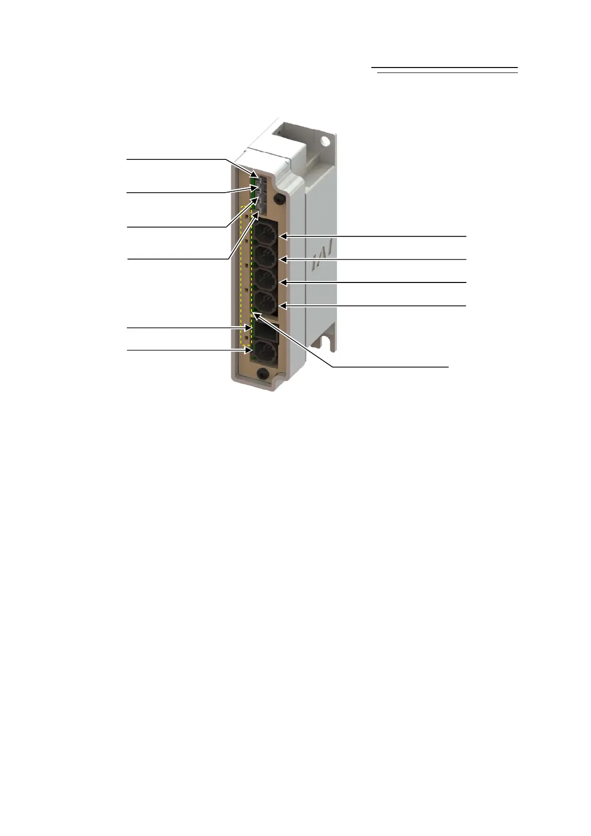
1) Hub Control Connector
It is a connector to supply power and control signals (24V DC control power supply, 24V DC
motor power supply, communication line, brake release signal and emergency stop status) from
the gateway to a hub.
2) Hub Power Supply Connector
It is a connector to supply 24V DC motor power from the gateway to a hub unit.
3) Breake Release Switch AXIS0
4) Breake Release Switch AXIS1
5) Breake Release Switch AXIS2
6) Breake Release Switch AXIS3
It is a switch to breake release swich. Four switches are equipped for AXIS 0 to 4.
7) RCP6S Connector AXIS3
8) RCP6S Connector AXIS2
9) RCP6S Connector AXIS1
10) RCP6S Connector AXIS0
It is a connector to supply the power and the control signals (24V DC control power supply, 24V
DC motor power supply, communication line, brake release signal and emergency stop status)
from a hub to connected axes.
* Refer to Chapter 2 Wiring for details for such as connector codes and pin assignments etc.
6) Breake Release
Swicth AXIS3
) Breake Release
Swicth AXIS2
4) Breake Release
Swicth AXIS1
2) Hub Power
Supply Connector
1) Hub Control Connector
) Breake Release
Swicth AXIS0
7) RCP6S Connector AXIS3
8) RCP6S Connector AXIS2
9) RCP6S Connector AXIS1
10) RCP6S Connector AXIS0
11) Axis Status Display LED

 Loading...