Fieldbus Communication
17
RCP6
4. RCP6S Gateway Controllers
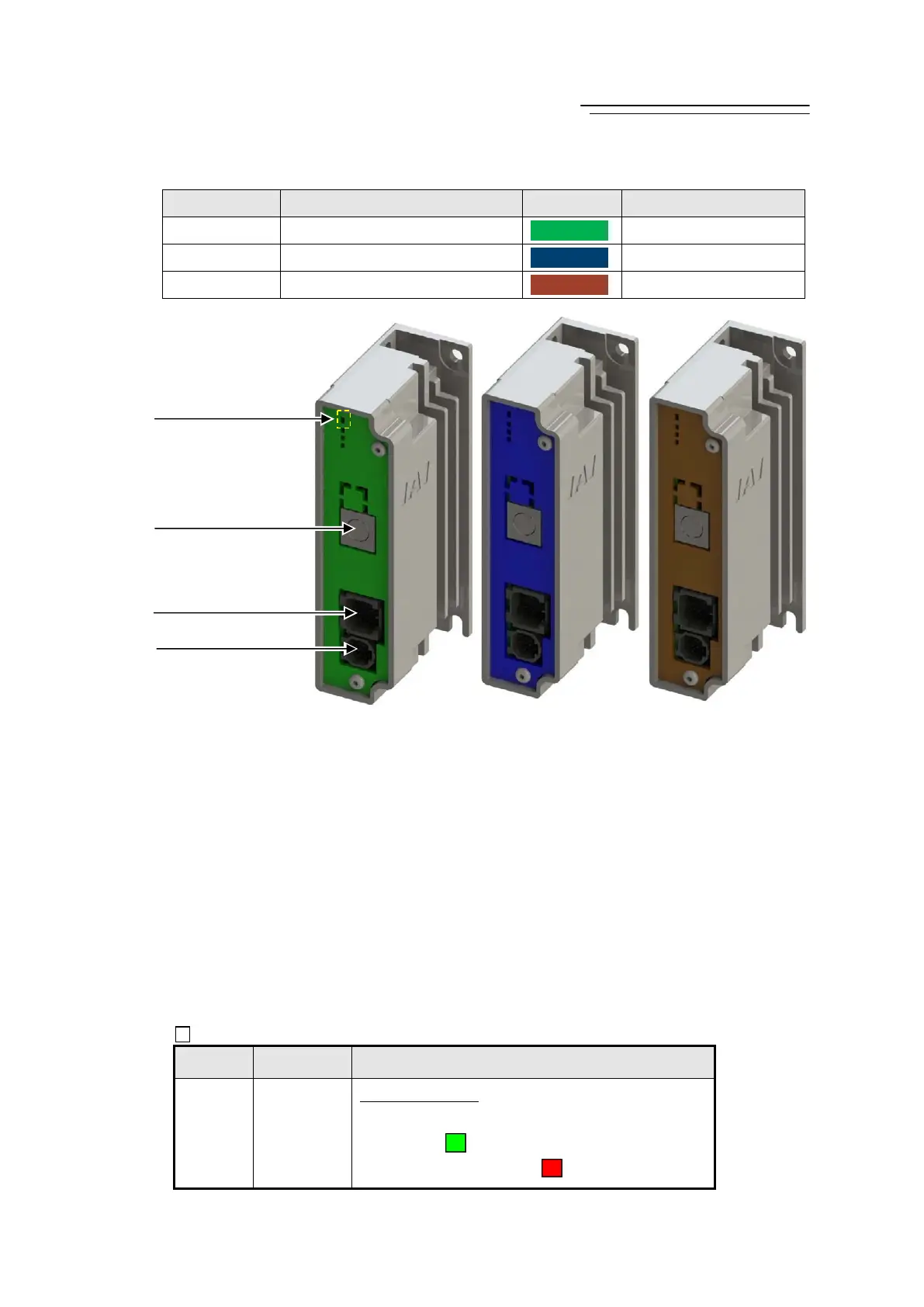
1) Power Connector
It is a connector to supply power and send control signals (control power 24V DC, motor power
24DC, communication line, brake release signal and emergency stop status) from the hub unit or
gateway unit to controllers for RCP6S Gateway.
2) Axis Control Connector
It is a connector to supply power and send control signals (control power 24V DC, motor power
24DC, communication line, brake release signal and emergency stop status) from a controller for
RCP6S Gateway to actuators.
3) SIO Connector
It is a connector to connect such as a teaching pendant or PC.
* Refer to Chapter 2 Wiring for details for such as connector codes and pin assignments etc.
4) Status Display LED
It shows the status of the RCP6S Gateway controllers.
: Illuminating ×: OFF
Symbol LED Display Color and Operation Status
LED1 SV/ALM
Servo ON/Alarm
Servo OFF ( × OFF)
Servo ON (
Green Illuminating)
Alarm, Emergency Stop (
Red Illuminating)
Model Type Panel Color Applicable Actuator
RCM-P6PC Pulse Motor Type
RCP2 to 6
RCM-P6AC Servo Motor Type
RCA and RCA2
RCM-P6DC Brushless DC Electric Motor
RCD
2) Axis Control Connector
3) SIO Connector
1) Power Connector
4) Status Display LED
RCM
-P6DC
RCM
-P6AC
RCM
-P6PC

 Loading...