2. Wiring
Fieldbus Communication
54
RCP6
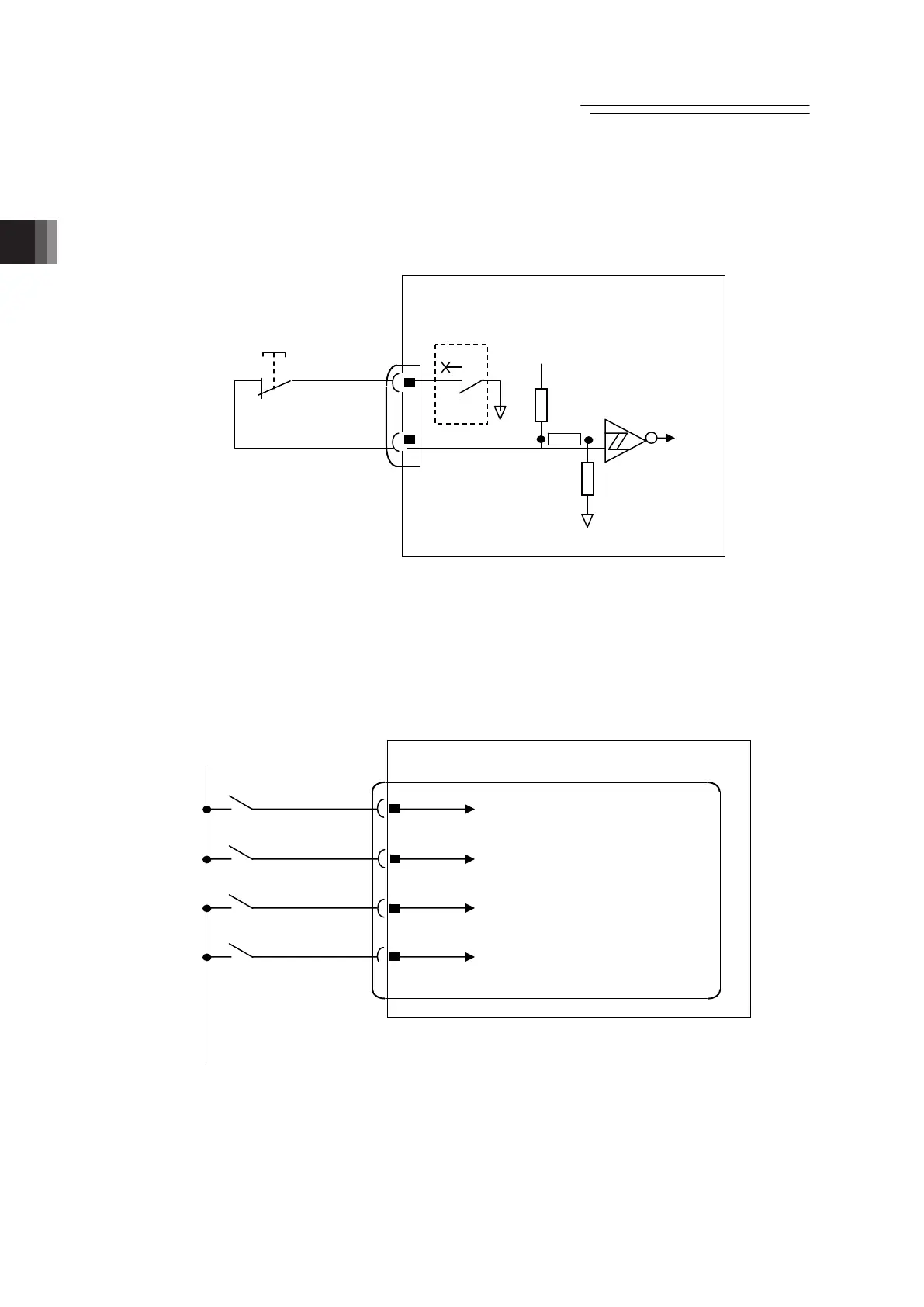
[3] Layout for Mode Switchover Circuit
When a switchover of the operation modes (AUTO/MANU) is required with an external input,
connect a device such as a switch between AUTO/MANU + terminal and AUTO/MANU –
terminal.
If not switching externally, apply a jumper on AUTO/MANU + terminal and AUTO/MANU –
terminal.
[4] Layout for External Brake Input Circuit
Lay out the circuit when an external compulsory brake release with using an actuator equipped
with a brake is desired. It is not necessary if an external release is not required.
This is how to lay out the brake release when connected directly to the gateway unit.
This input will be invalid in case that a hub is connected. In such a case, release the brake on
the brake release switch on a hub unit.
0V is in common with the control power supply.
Brakes should be available for release if the control power is supplied to RCP6S Gateway Unit.
6
7
13
14
xis No.0 Brake Release Input Circuit
xis No.12 Brake Release Input Circuit
xis No.8 Brake Release Input Circuit
xis No.4 Brake Release Input Circuit
RCP6S GW
BK_AX0
24V
System I/O Connector
BK_AX4
BK_AX12
BK_AX8
RCP6S GW
UTO/MANU-
UTO/MANU+
System I/O Connector
Operation Mode Setting
(AUTO/MANU) Switch
MANU
20KΩ
UTO
100KΩ
24V
External
Operation Mode
Setting
(AUTO/MANU)
Switch
5.6KΩ
OFF: AUTO
ON : MANU
Internal
Power
Supply
8
9

 Loading...