11. Wait up to 5 minutes for the Storage Manager software to recognize the new
controller.
12. Connect the host interface cables to the controller. See “Cabling the DS3500
storage subsystem” on page 31 for more information.
13. Ensure that all storage enclosure connections have been completed (see the
dual-controller topologies in “DS3500 storage subsystem drive cabling
topologies” on page 50); then, connect the SAS drive expansion cable from the
right ESM in the last storage enclosure in the chain to the drive expansion
port on controller B of the DS3500.
14. Wait up to 5 to 10 minutes for the Storage Manager software to report the
drives and the redundant drive path.
15. Add the storage subsystem back to the Storage Manager. The secondary IP
can be set depending on whether the default fabric infrastructure or DHCP is
used in the storage subsystem. If required, change the IP setting.
16. Verify the state of the LEDs on the newly inserted controller. See “Controller
LEDs” on page 90. You can also use the Subsystem Management window to
identify any new faults. Do any storage subsystems have a fault (Needs
Attention) status?
v Yes: Click Recovery Guru in the Subsystem Management window toolbar,
and complete the recovery procedure. If the problem remains, contact your
IBM technical-support representative.
v No: Go to step 17.
17. Use the Storage Manager software to print a new storage subsystem profile.
Replacing a controller
Use this procedure to replace a controller that has failed.
Before you replace a controller, perform the following prerequisite tasks:
Familiarize yourself with the steps to access the Storage Manager software. For
details about installing and using the Storage Manager software, see the IBM
System Storage DS Storage Manager Version 10 Installation and Host Support Guide (for
DS Storage Manager V10.77 or earlier) or the IBM System Storage DS Storage
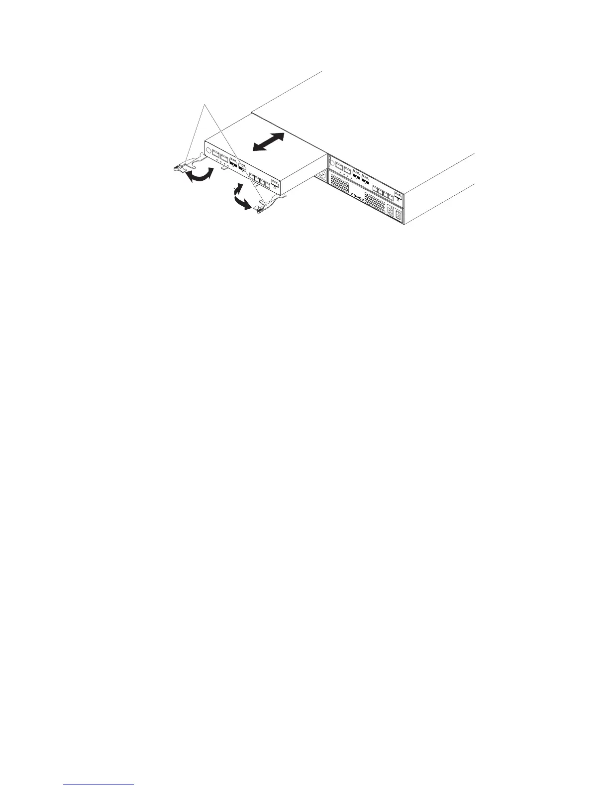
Release
levers
a. Ensure that the release levers on the controller are in the open position.
b. Slide the controller into the bay until it stops.
c. Push the release levers to the closed position.
Figure 90. Installing a controller
Chapter 5. Replacing components 109